
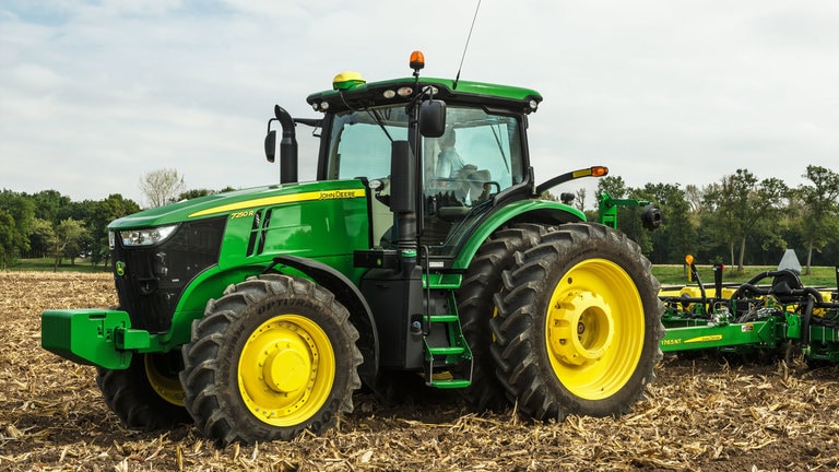
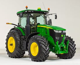
7250R Tractor
- 250 Engine hp
- John Deere PowerTech™ 6.8L PSS
- Choice of e23™ PowerShift, or Infinitely Variable Transmission (IVT™)
- MFWD, or Triple Link Suspension Plus (TLS™)
Features
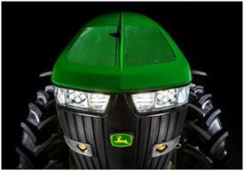
Lighting packages provide 360 degrees of coverage for maximum productivity
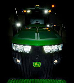 Premium lights
The 7R, 8R, and 8RT Series Tractors feature two lighting package options:
- Standard
- Premium
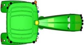
The cab lighting pattern provides 330 degrees of coverage while the hood lighting provides the remaining 30 degrees for completely programmable 360-degree, stadium-style lighting. This ensures there are no dead zones or lighting adjustments needed. The lighting configurations are available to match various applications and ensure maximum around-the-clock productivity.
Bulb housings are large, allowing for optimum total lumens and available light. The standard lighting packages use 65-W halogen bulbs, whereas the premium lighting package uses light-emitting diode (LED) lights. In the premium lighting package, these tractors take advantage of the high-performing and efficient LED technology.
The low- and high-beam driving/work lights are adjustable. Please refer to the electrical section in the operator’s manual for complete details on adjusting lights.
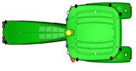
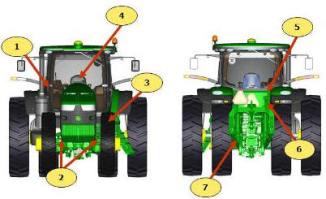
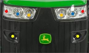 7R/8R/8RT lighting
Yellow circles
- All lighting packages: 65-W halogen: road low beam
Red circles
- Standard: 65-W halogen
- Premium: LED
Blue circles
- Standard: 65-W halogen; field and road high beams
- Premium: LED
Orange circles
- Standard: blank
- Premium: LED
|


Standard lighting
 Standard lighting (8R)
 Standard lighting (7R)
Six front grill-mounted lights:
- Two 65-W low-beam driving/work lights (mid grill screen)
- Two 65-W high-beam driving/work lights (top of grill screen, hood mounted)
- Two front corner-facing halogen work lights (top of grill screen, hood mounted)
10 cab roof-mounted lights:
- Two rear-facing 65-W floodlights
- Four side-facing 65-W floodlights
- Four corner-facing amber lights
Other lights:
- Two rear fender-mounted floodlights
- Two rear turn signal and brake/tail lights (fender mounted)
- Two folding-extremity lights
Plus these lights:
- Two adjustable front roof 65-W halogen floodlights
- Two front belt-line floodlights
- Rotary beacon light
Premium lighting
Eight front grill-mounted lights:
- Two 65-W low-beam halogen driving/work lights (mid grill screen)
- Two LED high-beam driving/work lights (top of grill screen, hood mounted)
- Two front corner-facing LED work lights (top of grill screen, hood mounted)
- Two front-facing LED working lights (top of grill screen, hood mounted, inner position on the sides)
12 cab roof-mounted lights:
- Four side-facing LED lights
- Four corner-facing amber lights
- Two rear-facing LED lights
- Two adjustable front roof LED lights
Other lights:
- Two rear fender-mounted LED lights
- Two rear turn signal and brake lights (fender mounted)
- Two folding-extremity lights
- Two front belt-line LED floodlights
- Rotary beacon light
The premium lighting package replaces all previous halogen and HID lights with LED lights. The only lights that are not LED are the low-beam driving lights, they remain halogen. This allows each LED light to work at a lower temperature and no one light works harder than any other. The uniformity in LED coverage allows only one type of light output surrounding the tractor.
The lighting pattern in the premium package provides industry-leading performance in nighttime visibility. LED bulbs provide maximum brightness and a true color output for excellent field definition that is easy on the operator's eyes.
The LED lights provide 40 percent greater coverage width and 10 percent more light coverage in the rear. LED lighting packages use 45 percent less amps than standard halogen lights and have an increased life expectancy over HID lights which leads to lower costs of ownership over the life of the tractor.
NOTE: Lighting packages may vary depending on region.
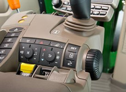
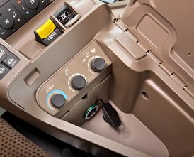
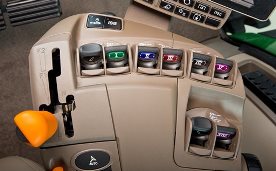
Selecting a lighting mode/programmable lighting
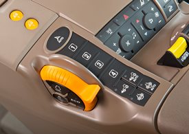
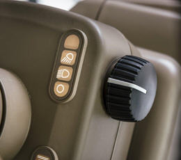 Lighting mode selector
Operators can quickly select a lighting mode on the steering console:
- Lights, off position
- Road lights
- Field lights
 The CommandCenter™ display
The CommandCenter display allows operators to customize light settings. Operators can select only the lights they need or want for a given application and store these settings. The operator-programmed configurations can then be turned on or off with the push of a button on the CommandARM™ controls.
- Programmable field lights 1
- Programmable field lights 2
- Beacon light
- Emergency flashers
NOTE: Road/loader lights are also referred to as high-mounted driving lights for use in front hitch applications that obscure the headlights. See the Attachments section.
The battery power saver feature is also standard. When the engine is off and the outside lights have been left on, this feature is designed to avoid battery run down.
After the lights have been left on for 30 minutes and the key is in the off position, the lights cycle or blink on and off five times as an alert. The lights continue to illuminate for one more minute and then automatically shut off to protect the battery.
Field-installed options
Field-installed options are also available. To find this information, use the Build Your own Configurator application for US/Canada or Build & Price in John Deere Sales Centre for Australia/NZ.
Programmable exit lighting
Another feature is programmable exit lighting. Exit lighting allows the lights outside the cab to stay on for up to 300 seconds. They can be programmed in increments from 0 to 300 seconds.
Refer to the operator’s manual for complete instructions on programming field, driving, and exit lighting.
| Option code | Description |
| 7201 | Standard lighting |
| 7206 | Premium lighting |
Steering
The steering system uses load sensing of hydraulic pressure required to efficiently complete the designated tasks. The pressure- and flow- compensating pump produces excellent stationary or creeping ground speed steering response to handle demanding applications.
ActiveCommand Steering (ACS™)
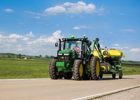 7R in transport
With ACS, John Deere has designed one of the most robust and full-encompassing steering system in the industry. Whether in the field or on the road, ACS reduces steering effort, which can result in reduced operator fatigue and can improve operator comfort.
There are four key features of the ACS system:
Dynamic road wheel offset
- A gyroscope senses tractor yaw and can automatically make small steering adjustments to provide unprecedented line-holding abilities. Drive down a bumpy road and experience how ACS makes it easier to keep the tractor straight, even over rough terrain. ACS delivers the ultimate in comfort.
- ACS works to prevent oversteering when a sudden obstacle causes the operator to make a quick steering reaction.
Variable ratio steering
- Approximately 3.5 turns lock to lock at in-field speeds for quick headland turns.
- Approximately 5 turns lock to lock at transport speeds.
Elimination of steering slop and hand wheel drift
- Steering wheel drift and slop are eliminated with the ACS electronic control system.
Variable effort steering
- Steering wheel resistance automatically changes with ground speed to deliver light steering effort at slower speeds for less effort during headland turns, and higher steering wheel torque at transport speeds for better operator comfort.
A fail operational system
The ACS system is fail operational, which means steering is still functional in the event of any single-point failure. John Deere has gone to great lengths to help ensure the operator can steer the tractor if something goes wrong in the steering system.
For example, if the primary controller fails, a second controller takes over. If power from the alternator is lost, the battery resumes control. If the engine quits running and is unable to supply hydraulic oil to the system, an electric-driven backup pump is used to supply the oil.
 ACS components
The ACS system consists of several key components:
- Gyroscope: this is used to measure the yaw rate (turn rate) of the tractor during transport speeds.
- Road-wheel angle sensors: these sensors simply measure the steer angle of the tractor.
- Power supply module: this module distributes the power of the battery and alternator throughout the ACS system.
- Hand-wheel angle sensors and tactile feedback unit: this includes the steering wheel position sensors and a brake, which can increase or decrease resistance dependent on speed. Lighter feedback is desired during normal field use, and slightly heavier feedback is desired during transport and while the tractor is cornering at high speeds.
- Controllers: two controllers are located in the back of the tractor and are the brains of the system.
- Control valves: also known as steering valves, control valves are used to steer the tractor.
- Electric-drive backup pump: this pump supplies oil to the steering system, brakes, and park brakes (for towing) if there is no longer a sufficient oil supply to the steering and brakes.
Value of ACS
- Improves line holding when driving at transport speeds
- Fewer turns lock-to-lock: 3.5 turns lock-to-lock in the field for quicker headland turns and 5 turns lock-to-lock at transport speeds
- Eliminates hand-wheel backlash and drift
- Reduces steering effort, resulting in reduced operator fatigue
- Smaller hand-wheel diameter for improved operator comfort and visibility
- Maintains operator feel and touch points of traditional steering column system
- Fully integrates with AutoTrac™ guidance system
- Compatible with suspended and non-suspended front axles
- Compatible with wide- and narrow-section width tires
| Option code | Description |
| 1833 | John Deere ActiveCommand Steering (ACS) |
ActiveSeat™ seat utilizes electrohydraulic technology with air suspension
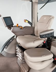 ActiveSeat and controls
John Deere’s ActiveSeat utilizes electrohydraulic technology in combination with air suspension, providing the operator with enhanced ride quality over standard air-suspension seats.
Operator movements are monitored in order to reduce vertical movement. An ActiveSeat suspension can isolate the operator from up to 90 percent of vertical movements typically seen in tractor applications.
The system uses a hydraulic cylinder that is connected to a control valve assembly. Electrohydraulic valves located in the control valve assembly automatically react to inputs from two sensors, a position sensor and an accelerometer. Inputs from these two sensors control oil flow from the tractor to the hydraulic cylinder to reduce the vertical movement of the operator.
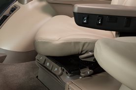 ActiveSeat left armrest
The John Deere ActiveSeat has many of the same features of the ComfortCommand™ seat with the addition of a ride firmness switch. The ride firmness switch is located on the left-hand armrest and replaces the suspension shock-dampening seat attenuation lever on the front right-hand side of the ComfortCommand seat controls.
The ride firmness switch has three positions: plus, minus, and mid position. The three positions provide three different levels of seat performance:
- The plus position provides the greatest degree of ride firmness. This position allows more of the tractor's inputs to be felt by the operator (slightly rougher ride).
- The minus position provides the least degree of ride firmness, allowing minimal tractor inputs to reach the operator, resulting in maximum seat performance.
- The mid position allows a balance between the plus (+) and minus (-) settings.
The ActiveSeat is also available as a heated leather seat for increased comfort and easier cleaning. For tractor applications where operating speed is not limited by the implement, the ActiveSeat can allow for faster field speeds and increased overall comfort and productivity.
NOTE: The John Deere ActiveSeat is not available on track tractors.
| Option code | Description |
| 2061 | Premium CommandView III Cab with Active Seat |
e23™ transmission
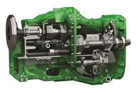 7R e23 transmission
The e23 transmission delivers smooth shifting and intuitive controls with Efficiency Manager™ feature in a reliable 23-speed PowerShift™ transmission. The e23 transmission is available for all 7R, 8R, and 8RT Series Tractors.
The e23 has evolved from more than 50 years of John Deere PowerShift technology. With more automatic features, the e23 is easy to operate for all levels of operator experience. For more advanced operators looking to customize the transmission to best fit their operation, the e23 offers a custom mode.
As the next generation of PowerShift technology, e23 delivers the strength to handle sudden, high-torque power loads while maintaining responsive, quick, and smooth shifts. The e23 with Efficiency Manager provides improved fluid efficiency and overall productivity with limited input from the operator.
e23 options
- e23 transmission 42 km/h (26 mph) with Efficiency Manager
- e23 transmission 50 km/h (31 mph) with Efficiency Manager
Even gear spacing for optimal performance
The e23 has 23 forward gears and 11 reverse gears, which are all evenly spaced. Forward gears are spaced 15 percent apart, while reverse gears are spaced approximately 30 percent apart, providing operators smooth shifting between gears. Even spacing improves efficiency and allows for smooth, automated shifts when using Efficiency Manager. The e23 can reach maximum forward ground speed in gear F20. As a result, gears F21-F23 maintain maximum ground speed at reduced engine rpms to save fuel.
e23 controls
The e23 is available with either a right-hand or left-hand reverser.
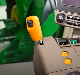
 Right-hand reverser
Right-hand reverser
A convenient, right-hand reverser is available with the e23 transmission. The reverser is located on the CommandARM™ as shown above.
- Forward direction selector
- Reverse direction selector
- Neutral position
- Electronic park lock
Right-hand reverser equipped models use three main controls to operate the tractor:
- Foot brake with integrated AutoClutch
- Set speed adjuster
- Gear selector control lever with integrated reverser
The right-hand reverser control strategy combines speed control and direction control into one multi-function lever that is conveniently located on the CommandARM. This is a good choice for most common field applications since tractor speed and direction are not constantly being adjusted by the operator.
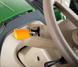
Left-hand reverser
 Left-hand reverser
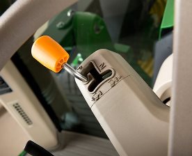
 Left-hand transmission lever
An easy-to-use left-hand reverser is available with the e23 transmission and includes the same functions as the right-hand reverser. The reverser control is located at the 10 o’clock position on the steering column for intuitive control.
The five-position, left-hand reverser column incorporates the following controls:
- Forward direction selector
- Reverse direction selector
- Neutral position
- Electronic park lock
Left-hand reverser equipped models use four main controls to operate the tractor:
- Foot brake with integrated AutoClutch™ function
- Set speed adjuster
- Gear selector control
- Multi-function left-hand reverser
The left-hand reverser control strategy separates the direction control lever from the speed/gear control lever on the CommandARM. This strategy is a good choice for operations requiring the right hand to run multiple operations on the CommandARM or applications requiring constant directional changes like loader work.
Determining which reverser is best suited for a specific operator depends on a few key factors. Consider the following to help choose between a left- or right-hand reverser.
- Operator preference and ergonomic benefits.
- Operators in loader applications might prefer a left-hand reverser since direction changes occur frequently while their hands are on the steering wheel (near the left-hand reverser location).
Producers primarily in row-crop applications using features like AutoTrac™ assisted steering system or operating with the seat swiveled to the right for easy access to monitors and displays might find the right-hand reverser more convenient. Speed and directional controls are in one location on the CommandARM.
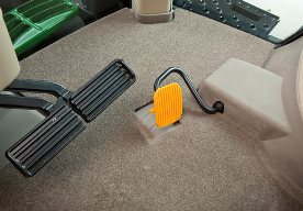
Foot brake with integrated AutoClutch function
The electrohydraulically controlled brakes on e23-equipped tractors have an integrated AutoClutch function.
- At low idle only, the tractor will stop by depressing only one brake pedal.
- Pressing both brakes (locked together) simultaneously will stop the tractor from any ground or engine speed.
Braking can be done on flat ground or steep slopes simply by using the brake pedals; it is not necessary to depress the clutch.
- It is recommended to lock the brake pedals together when operating on roads.
 |
| Foot brake with integrated AutoClutch |
AutoClutch sensitivity can be adjusted through the Generation 4 CommandCenter™ display. AutoClutch can be deactivated on e23 transmissions as well; however, it will be reactivated after every key start.
Stopping the tractor using AutoClutch
During transport, it may be desirable to use the AutoClutch feature to stop the tractor when approaching an intersection or turn. Braking the tractor using the AutoClutch at high ground speed and engine speed will require high brake-pedal force.
Rather than using AutoClutch alone, reduce the engine rpm and reduce the e23 to a slower commanded speed before applying the AutoClutch. This will help to reduce the force needed to stop the tractor with the AutoClutch. The tractor will accelerate to the previously commanded speed upon release of the AutoClutch, repositioning of the hand throttle and increasing the commanded speed.
NOTE: The preferred method of stopping heavy towed loads is to reduce the e23 commanded speed and lower engine rpm first, and then depress both brake pedals. (Brake pedals should be locked together.)
Using individual brake pedals - implement hook-up
Individual brake pedals can be used to assist slow-speed off-road turning, such as hooking up to an implement. At low idle, the AutoClutch feature will stop the tractor if the operator depresses only one brake pedal.
To assist in hooking up an implement, depress either brake pedal while slowly increasing engine speed until the desired turn is achieved. Returning engine speed to a low idle while continuing to depress one brake pedal will slow the tractor to a stop.
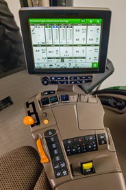
CommandCenter™ controls
 254-mm (10 in.) Generation 4 CommandCenter
The CommandCenter is the central information system for tractors and allows the operator to program various settings tailored to a specific operation.
To access the tractor’s transmission settings, press the transmission shortcut button on the CommandCenter shortcut bar.
 |
| CommandCenter transmission shortcut button |
Operating modes
The e23 application settings employ three modes to take full advantage of the engine-transmission communication: full auto mode, custom mode, and manual mode.
Full auto mode
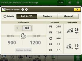 Full auto main page
Full AUTO mode enables the tractor to make adjustments to the transmission operating mode automatically, based on engine and transmission speed and the load on the tractor. This means the tractor will shift up and throttle back automatically to reach the desired ground speed efficiently. Operators have the ability to set the maximum forward and reverse speeds for the tractor in their particular application.
When shifting in full AUTO mode, the transmission shifts set speeds, meaning the transmission may not necessarily shift gears each time the lever is bumped. Efficiency Manager is automatically engaged while operating in full AUTO mode. As a result, shifting will not take the tractor out of Efficiency Manager in full AUTO mode.
Custom mode
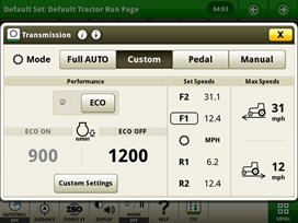 e23 custom transmission page
Custom mode allows operators to adjust operating parameters to meet their specific operation. Just like full AUTO mode, custom mode shifts set speeds meaning the transmission may not necessarily shift gears each time the lever is bumped. Efficiency manager is engaged automatically in custom mode.
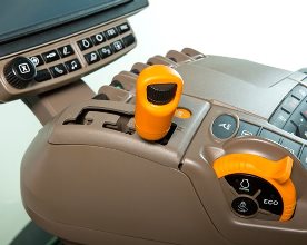
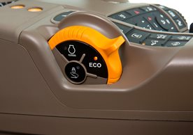
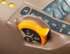 Eco button
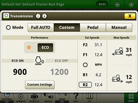 Display screen
In custom mode, eco allows two minimum engine speeds to be set. Operators can turn eco on and off by either pushing the eco button on the side of the throttle or by selecting eco in the transmission settings page of the CommandCenter. For example, operators may choose to turn eco on during transport to utilize a lower minimum engine speed and then turn eco off while operating in the field where a higher minimum engine speed is desired.
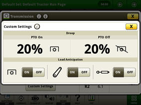 Custom settings page
In the advanced settings page, operators can customize the auto shift engine speed droop as a percentage of the full engine speed. In addition, the load anticipation feature can be enabled for the hitch engagement, hydraulic engagement, or both.
Manual mode
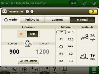 Manual mode page
Manual mode operates similar to a traditional PowerShift transmission. When shifting, the transmission shifts gears, not set speeds like full AUTO and custom mode. Manual mode also features efficiency manager when the operator engages set speed one or two on the CommandARM, as shown above in illustration.
When operating in manual mode with efficiency manager active, there is the option of turning eco on or eco off. This allows the operator to select two different minimum engine speeds. In the advanced settings page, operators can adjust auto shift engine speed droop and load anticipation, similar to custom mode.
Advanced transmission settings
Additional transmission settings can be customized to the operators’ specific desires.
AutoClutch sensitivity can be adjusted on the transmission settings page in the CommandCenter display. Operators can turn off AutoClutch or choose from high, medium, or low sensitivity. Operators can fine-tune AutoClutch by delaying the response time, based on load, travel speed, etcetera. This allows the trailer brakes to be applied before AutoClutch engages.
- High: for light or no trailer (load) – factory default
- Medium: for medium trailers (load)
- Low: for heavy trailers (load)
- AutoClutch Off: to operate e23 just like a traditional powershift
The AutoClutch sensitivity factory default-setting is set to high, which supports most operations.
AutoClutch sensitivity settings are available in all three modes – auto, custom, and manual.
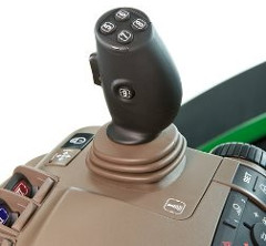
Efficiency manager
 |
| Set speed buttons and set speed adjuster |
Efficiency manager is automatically enabled in full AUTO and custom mode. Efficiency manager can be turned on in manual mode by selecting the set speed one or two on the CommandARM. The set speed adjuster on the top of the single-lever gear selector allows the operator to dial in the desired ground speed to establish set speed one or two in Efficiency Manager.
Efficiency manager allows the transmission to up or down shift and change engine rpm to maintain the set wheel speed. To reach the desired set speed, the throttle must be set to full engine rpm. This allows efficiency manager to shift the transmission and adjust engine speed to maintain the desired wheel speed. For more information on Efficiency Manager refer to the operator’s manual.
e23 operation
Both right-hand reverser and left-hand reverser control options provide full powershifts for on-the-go shifting; no need to stop or clutch when bump shifting or shuttle shifting between forward and reverse.
The single-lever shifter allows for quick and convenient shifting with minimal physical effort.
Shifts are made either by bumping the lever or by holding the lever in a forward or rearward position.
- Transmission is in neutral when the shift control or left-hand reverser is not in park, forward, or reverse.
- Operator presence feature prevents the transmission from going into gear when the operator is not seated or has the brake or clutch pedal depressed.
- Transmission can be programmed to start in 1F – 13F or 1R – 6R.
A forward gear between 1F and 13F may be preselected by depressing the clutch pedal and pushing or pulling the shift lever. The transmission will then start in the preselected forward gear when clutch pedal is released.
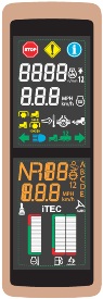 Cornerpost display
The cornerpost display shows the commanded gear instantaneously once selected.
| Option code | Description |
| 1493 | e23 Transmission 42 km/h (26 mph) with Efficiency Manager |
| 1494 | e23 Transmission 50 km/h (31 mph) with Efficiency Manager |
| 2701 | Right-hand Reverser Bump-Shift-Type Transmission Controls |
| 2702 | Left-hand Reverser Bump-Shift-Type Transmission Controls |
Rapid shifting
 Rapid shifting
When the tractor is working in a light-load condition, for example in transport, the transmission can be shifted rapidly by bumping the shift lever.
To reach transport speeds quickly:
- Depress clutch pedal and rapidly bump shift lever to 13F
- Transmission will shift directly to 13F when clutch pedal is released
- Transmission will skip some gears as it keeps up with the operator’s command, allowing the tractor to accelerate to transport speed quickly
- Once tractor is underway in 13F, bump the shift lever to reach desired ground speed
Double shifting
The transmission can skip a gear when operating under load by double bumping the shift lever.
- This aids the ease of deceleration/acceleration when approaching and departing headland turns.
Ground speed matching
When the tractor is slowing down and the clutch pedal is depressed, the transmission will match a gear to the ground speed of the tractor when the clutch is released. Ground speed matching only engages in gears 13F higher.
Setting start-up gears
The transmission defaults to 8F and 3R at start-up. However, these default start-up gears can be adjusted from 1-13F and 1-6R through the CommandCenter. Refer to the operator’s manual for additional information.
 |
| Start-up gears in advanced settings |
Releasing the park brake
The e23 transmission utilizes a spring-engaged/hydraulically-disengaged park brake. The park brake control feature prevents accidental park brake engagement when tractor is moving at high speed.
On tractors equipped with air brakes, the park brake automatically activates the air brake system.
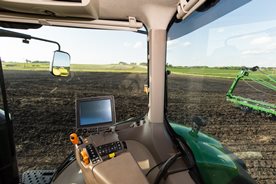
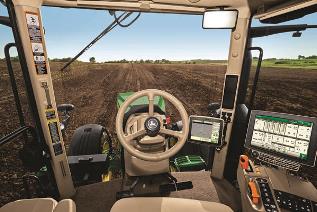
Standard CommandView™ III cab offers unsurpassed amenities
 CommandView III cab
The Standard CommandView III cab offers unsurpassed visibility, operator comfort, control placement, and ride and sound quality.
Features:
- ComfortCommand™ seat with air suspension, lumbar support, swivel, fore-aft and lateral attenuation, backrest angle adjustment, adjustable left-hand armrest, and 40-degree right-hand seat swivel
- Operator presence system that warns if the operator is out of the seat while operating key functions
- Folding instructional seat
- CommandARM™ console with integrated controls
- 4100 or 4600 Generation 4 CommandCenter™ display
- Behind-the-seat storage
- Left-hand storage compartment
- Passive noise reduction system
- Service ADVISOR™ data port
- Tilt/telescoping steering wheel with position memory
- Swing-out rear window that opens 30 degrees
- Right- and left-outside mirrors (manually adjustable mirror head)
- Monitor mounts on right-hand front post and rear cab post
- Standard radio package, including AM/FM stereo and weatherband with remote controls, auxiliary input jack, four speakers, and an external antenna
- Laminated glass
- Air conditioner and heater with automatic temperature controls (ATC)
- Two 12-V convenience outlet (cigarette lighter style)
- One 12-V three-pin outlet with adapter (provides switched and unswitched power)
- One International Organization for Standardization (ISO) nine-pin connector
- Power strip with convenience plug adapter
- Hitch control lever lock and selective control lever lock
- Two-speed and intermittent front and rear wiper with washer
- Front pull-down sunshade
- Digital cornerpost display with:
- Fuel level gauge, including low fuel warning
- Temperature gauge
- Diesel exhaust fluid (DEF) gauge, including low DEF warning
- Engine rpm
- Transmission commanded gear or speed
- Vehicle system functions, such as iTEC™ system, that are operating
- Inside-mounted rearview mirror
- Beverage holders sized to accommodate various containers
- Interior left-hand dome light
ComfortCommand seat
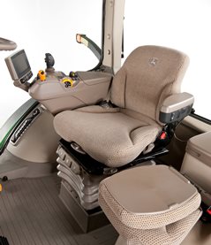 ComfortCommand seat
ComfortCommand seat improves ride quality and helps to reduce operator fatigue.
Features include:
- Armrests, lumbar support, and backrest angle are easily adjusted to match operator preference.
- Shock absorbers dampen the motion effect of the tractor for an improved ride.
- Seat height adjustments are conveniently located on the left armrest.
- Fore-aft adjustment is easy to reach located on the left front of the seat.
- Swivel adjustment, located on the front of the seat, allows the seat to be swiveled 40 degrees to the right or eight degrees to the left of the center position.
- Operator presence switch warns if the operator is out of the seat while operating key functions.
- Seat belt retractor.
- Centered cab seat provides excellent over-shoulder visibility.
- Adjustable shock absorber permits ride adjustment from soft to firm to match the operator's desired comfort level.
- Removable cushions allow for easy cleaning.
 Fingertip paddle pots
 Encoder wheel
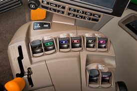
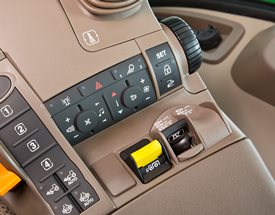
CommandARM
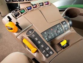 CommandARM controls
John Deere 7R and 8R Series Tractors feature the CommandARM with integrated Generation 4 CommandCenter display. The control layout of the CommandARM utilizes a clean and efficient design which groups controls by function and builds upon John Deere’s history of intuitive and ergonomic control placement and operation. The design of the CommandARM allows for a 40 degree right seat swivel and adjustable positioning matching the operator’s preference.
Controls located on the CommandARM include:
- Engine throttle
- FieldCruise™ system
- Minimum engine speed – CommandQuad™ transmission, 16-speed PowerShift™ transmission (PST), e23™ transmission
- Eco mode – Infinitely Variable Transmission (IVT™)
- Foot pedal lock (if equipped)
- Transmission control
- Hitch/selective control valve (SCV) controls
- Rotary encoder hitch control
- Power take-off (PTO) controls
- Mechanical front-wheel drive (MFWD) on/automatic
- Differential lock on/automatic
- iTEC sequence switches
- AutoTrac™ assisted steering system resume switch (if equipped)
- Joystick (if equipped)
- Radio
- Beacon light on/off
- Hazard lights on/off
- Field lights 1/2
- Heating, ventilation, air conditioning (HVAC) system
Transmission controls
John Deere 7R Series Tractors with CommandQuad transmissions feature a left-hand reverser. 8R Series Tractors equipped with 16-speed PST are equipped with right-hand reverser. 7R Series Tractors equipped with e23 PST offer a left- or right-hand reverser. 7R or 8R Series Tractors equipped with AutoPowr™/IVT transmissions are offered with either a left-hand or a right-hand reverser.
The transmission control lever is placed on the left side of the CommandARM closest to the operator for convenient setting and adjustment.
 Left-hand CommandQuad/e23 reverser
 Right-hand IVT and PST reverser
 16-speed PST right-hand reverser
Hydraulic and hitch controls
Hydraulic and hitch controls utilize fingertip paddle pots for raise/lower and extend/retract functions. An optional crossgate joystick replaces fingertip paddle pots for control of SCVs and allows for programmable hydraulic functionality according to operator preference. Rear hitch position can also be controlled with the encoder wheel located on the right side of the CommandARM. The encoder wheel allows for finite positioning of the rear 3-point hitch.
Three buttons near the encoder are for hitch set, lock, and return to height. Adjustment knobs for the 3-point hitch are located under the cover for the CommandARM control's storage compartment and allow for adjustment of the rate of drop, hitch height limit, and depth control.
 Hitch controls
 Optional crossgate joystick
Throttle
The throttle design incorporates buttons which control FieldCruise speed, foot pedal mode (if equipped), and transmission eco settings.
 Throttle
 Foot throttle
Tractor function controls
Located just to the right of the throttle is the AutoTrac activation button and four sequence controls for iTEC functions. Behind the iTEC sequence controls, there are buttons which control the activation and deactivation of MFWD and differential lock.
 AutoTrac resume and iTEC strip
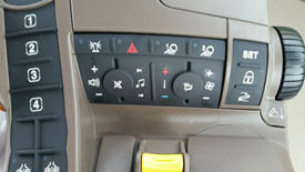
Controls for radio, lights, rotary beacon (if equipped), hazard flashers, and HVAC system are located to the center-right on the CommandARM, along with PTO for both front (if equipped) and rear PTO.
 Radio, HVAC, hazard flashers, and PTO controls
Seat swivel
The design of the CommandARM allows for up to 40 degrees of right-hand seat swivel.
 Seat swivel
CommandCenter
Generation 4 CommandCenter
The Generation 4 CommandCenter features fast adjustment of tractor functions and controls and are integrated into the CommandARM to create a seamless control center. The 4100 CommandCenter features a 178-mm (7-in.) touchscreen display and is standard equipment on 7210R and 7230R models, while the 4600 CommandCenter features a 154-mm (10-in.) touchscreen and is standard equipment on 7250R – 7310R models, as well as all 8R and 8RT models.
The following functions can be adjusted using the CommandCenter display:
- Hydraulic settings
- Hitch settings
- Transmission settings
- FieldCruise
- iTEC programming functions
- Radio
- Lights
The 7R Series cooling system
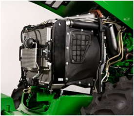 7R Series cooling package
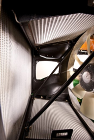 Pull-style fan and radiator access
The 7R Series Tractors feature an increased front area (IFA) cooling system that utilizes a pull-style fan that improves cooling efficiency over an increased surface area that provides better cooling capacity and reduces fan noise during increased power levels or while under heavy loads.
 Hood screen area
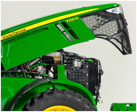 Engine hood with side shields
The 7R Series Tractors also have an increased screen area on the hood and redesigned side shields to help reduce debris buildup. The new cooling system provides easy, cooler cleanout and service accessibility without sacrifice to turning radius or front hitch and front power take-off (PTO) applications.
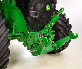
Front hitch options fit a variety of applications
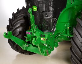 7R Series Tractor with front hitch
The 7R Series Tractors offer two front hitch options to best fit a variety of applications.
Standard (non-ground-engaging) hitch option for applications including, but not limited to:
- Front-mounted mowers, toppers, and snow blowers
- Carrying front seed hoppers and plow packers
- Carrying front ballast
- Operating light-draft implements
Premium (ground-engaging) hitch option for applications including, but not limited to:
- Operating primary tillage equipment and standard blades
Premium hitches include a push bar and heavier lift arms:
- Hitches with zero front auxiliary valves include one mid-mount valve.
- Hitches with one front auxiliary valve include two mid-mount valves.
- Hitches with two front auxiliary valves include three mid-mount valves.
To ensure adequate hydraulic availability, up to two selective control valves (SCVs) can be included with a front hitch.
Joystick control
 Paddle pot SCV
Tractors equipped with a factory front hitch have the option of selecting a joystick control or paddle pot SCV controls. The joystick control is not compatible with the sixth rear electrohydraulic SCV because of the CommandARM™ controls space required for the front hitch joystick.
Features of John Deere factory-installed front hitches include:
|
Standard |
Premium |
Lift capacity at ball ends (ISO) |
5200 kg (11,464 lb) |
5200 kg (11,464 lb) |
Lift range |
750 mm (29.5 in.) |
750 mm (29.5 in.) |
Overhang when folded |
55 mm (2.2 in.) |
55 mm (2.2 in.) |
Approach angle (depending on tire and axle setup) |
25.5 - 38.7 degrees |
25.5 - 38.7 degrees |
Reinforcing push bar |
Field-installed option |
Standard |
Auxiliary valve with front couplers |
Optional |
Standard |
Category 3N hitch |
Standard |
Standard |
7-pin connector - for implement lights |
Standard |
Standard |
9-pin harness and connector (ISO) |
Field-installed option |
Field-installed option |
Front-mounted remote switch |
Standard |
Standard |
Hitch damping |
Triple-Link Suspension (TLS™) axle, same effect |
TLS axle, same effect |
Hydraulic mode select |
Single and dual |
Single and dual |
Electronic position control |
Yes |
Yes |
Full ground clearance |
Yes |
Yes* |
iTEC™ compatible |
Yes |
Yes |
Power take-off (PTO) compatible |
Yes |
Yes |
Installed weight (with push bar)** |
-- |
455 kg (1003 lb) |
Installed weight (no push bar)** |
345 kg (760 lb) |
-- |
*Hitches with a push bar maintain front axle to ground clearance for row-crop applications and can be used with ground-engaging implements, including primary tillage implements and standard blades.
**Equals weight of added hitch components.
The integrated and styled compact hitch design maintains full maneuverability even with the larger front tires. The hitch extends only 55-mm (2.2-in.) ahead of the front support when the arms are folded.
Standard (carrier version) hitches can be converted to a premium (ground-engaging) hitch by ordering and field installing a conversion kit that includes push bar and heavier lift arms.
All factory-installed front hitches are capable of single- and dual-acting hydraulic cylinder modes. This allows the operator the flexibility to choose the correct mode for a variety of front hitch applications. Single acting provides hydraulic force for retracting the front hitch cylinders and allows front implements to follow the contour of the ground or surface. For example, this would be the correct mode for a front-mounted snow blower. Dual acting provides hydraulic force in retracting and extending the front hitch cylinders to provide down force for ground-engaging implements.
Additional hitch features include:
- Integrated and protected routing of oil lines
- Category 3 top link with storage position
- Integrated towing clevis with pin
- Compatible with group 42 - 44 front tires
 7R position sensing
The 7R with front hitch comes equipped with position sensing that allows operators the ability to establish an upper height limit set point and lower limit set point through CommandCenter™ display. Position sensing maintains the height of the hitch arms based on the set points.
Position sensing provides the following benefits:
- Add to iTEC™ display sequence (raise/lower set points)
- Limit height for front-PTO implement (stay within desirable driveline angles)
- Set lower position for ground-engaging depth or blade position
- Maintain set height without added fixed link (position will auto correct)
- Prevent inadvertent hitch operation outside of desired range of motion (takes guesswork out of placing height of front implement)
- Less fatiguing for repetitive-type work where the same position is required over and over
For a 9-pin connector, order kit RE322555. The kit includes all necessary components and allows ISO implement communication.
NOTE: 7R Series Tractors with a factory-installed front hitch do not ship with a front weight support.
Front hitch – Field-installed options:
For more information on ordering a front hitch ready configuration, refer to Attachments, front hitch/power take-off (PTO) ready
For tractors ordered non-hitch or non-hitch ready please contact LaForge® company for front hitch options.
Laforge Systems Inc.
4425-C Treat Blvd. #230
Concord, California 94521
Phone: (925) 827-2010 or 1-800-422-5636
Web site: www.fronthitch.com
LaForge is a trademark of Laforge Corporation.
Front hitch options:
- Standard front hitch with zero front couplers, 5200-kg (11,450-lb) maximum lift capacity at hitch balls
- NOTE: 3150-kg (6944-lb) International Organization for Standardization (ISO) lift capacity.
Less push bar (hitch raise/lower hard plumbed to mid-mount valve)
Includes zero front auxiliary couplers.
ISOBUS connector available through Parts.
- NOTE: 3150-kg (6944-lb) International Organization for Standardization (ISO) lift capacity.
- Standard front hitch with one front auxiliary coupler, 5200-kg (11,450-lb) maximum lift capacity at hitch balls
- NOTE: 3150-kg (6944-lb-) ISO lift capacity.
Less push bar (hitch raise/lower hard plumbed to mid-mount valve)
Includes one front auxiliary couplers.
ISOBUS connector available through Parts.
- NOTE: 3150-kg (6944-lb-) ISO lift capacity.
- Premium front hitch with one front auxiliary coupler, 5200-kg (11,450-lb) maximum lift capacity at hitch balls
- NOTE: 3150-kg (6944-lb) ISO lift capacity.
Includes push bar (hitch raise/lower hard plumbed to mid-mount valve)
Includes one front auxiliary couplers.
ISOBUS connector available through Parts.
- NOTE: 3150-kg (6944-lb) ISO lift capacity.
- Standard front hitch with two front auxiliary couplers, 5200-kg (11,450-lb) maximum lift capacity at hitch balls
- NOTE: 3150-kg (6944-lb) ISO lift capacity.
Less push bar (hitch raise/lower hard plumbed to mid-mount valve)
Includes two front auxiliary couplers.
ISOBUS connector available through Parts.
- NOTE: 3150-kg (6944-lb) ISO lift capacity.
- Premium front hitch with two front auxiliary coupler, 5200-kg (11,450-lb) maximum lift capacity at hitch balls
- NOTE: 3150-kg (6944-lb) ISO lift capacity.
Includes push bar (hitch raise/lower hard plumbed to mid-mount valve).
Includes two front auxiliary couplers.
ISOBUS connector available through Parts.
- NOTE: 3150-kg (6944-lb) ISO lift capacity.
- CommandARM™ paddle pot SCV controls
- NOTE: Not compatible with joystick control.
Provides proportional paddle pot SCV control for mid-mount valve(s).
- NOTE: Not compatible with joystick control.
- Joystick control
- NOTE: Does not include mid-mount valve or loader-ready components.
ISOBUS compatible.
Not compatible with six rear SCVs.
Not compatible with CommandARM SCV controls.
- NOTE: Does not include mid-mount valve or loader-ready components.
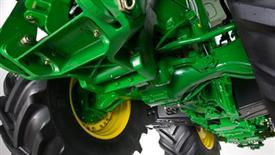
Triple-Link Suspension Plus (TLS™ Plus)
 7R with TLS Plus
The optional TLS Plus is a fully integrated, self-leveling front suspension system available on 7R Series Tractors equipped with the 1300 mechanical front-wheel drive (MFWD) axle. TLS Plus provides exclusive front suspension using a hydro-pneumatic self-leveling system to increase productivity and improve ride dramatically. TLS Plus provides more control over the front suspension of the tractor.
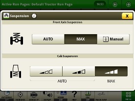 CommandCenter screen
In the Generation 4 CommandCenter™, the operator is able to select maximum pressure to accommodate for the transfer of heavy loads with minimal front axle movement.
TLS Plus increases both transport and field productivity with superior stability, ride, and comfort. Loader operators appreciate the enhanced performance when transporting bales or a full bucket of silage. In the field, the TLS Plus front suspension maintains ground-to-tire contact, enabling more power to the ground.
The TLS Plus front axle is available with or without wet-disc front brakes. While TLS Plus is available on all 7R Series Large-Frame Tractors, it is a requirement for the following:
31-mph/50K CommandQuad™ Eco
31–mph/50K e23™
31–mph/50K infinitely variable transmission (IVT™)
TLS Plus components
 7R with TLS Plus
Two double-acting-control cylinders act independently or together to dampen shock loads, while supplying a constant down force on the axle for better traction. In addition to the cylinders, a pan-hard rod limits lateral motion while an electronic sensor signals a priority valve to automatically move the control cylinders as needed.
The cast driveline draft member controls fore-aft suspension of the axle. This heavy-duty conical casting encloses the entire driveline and transfers longitudinal forces to the tractor's center of gravity.
 1300 axle with TLS Plus
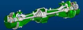 1300 axle cutaway with TLS Plus
Operating characteristics:
- TLS Plus self-levels at engine start-up with the implement attached and the hitch in the raised or lowered position.
- TLS Plus self-levels whenever the tractor speed exceeds 0.9 mph (1.5 km/h).
Differential lock
 CommandARM™ controls with automatic differential lock engaged
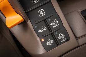 CommandARM controls with manual differential lock engaged
The differential lock is another feature of the 1300 Series MFWD axle with Triple-Link Suspension (TLS) PLUS, driveline shield, hydraulic on/off differential lock, and wet-disk front brakes. When the rear differential lock is engaged or disengaged, the front differential lock is also engaged or disengaged. This also includes a driveline shield.
If one wheel begins to slip, the differential lock can be engaged on the go and the axles are hydraulically locked together for maximum traction. There are two ways to engage the differential lock feature.
- Manual differential lock - differential lock can be engaged manually using a switch on the floor or by manual depressing button on CommandARM. When brakes are depressed, the differential lock will disengage
- Automatic Differential lock - when in auto mode, differential lock is engaged when the tractor is driving forward. Differential lock will disengage when front wheel turn angle meets disengage wheel angle setting defined by the operator via the CommandCenter or when either brake pedal is depressed. Differential lock will automatically engage when brakes are released or front wheels are turned straight.
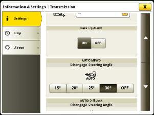 Automatic differential lock angle adjustment
Take advantage of the Generation 4 CommandCenter™ display, designed for efficiency
The Generation 4 CommandCenter was designed to provide a consistent user experience by providing full-screen viewing of more run page modules, shortcut keys, and precision agriculture capabilities.
Expect easier set-up, along with increased operator confidence, thanks to a simple, customizable interface. The improved design of the Generation 4 CommandCenter also aids in an optimal operating experience and maximizes uptime.
In order to increase your efficiency, take advantage of the following features offered by the Generation 4 CommandCenter:
Layout manager
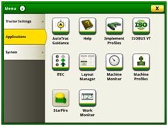 Layout manager selection page
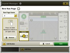 Layout manager module build
- Easily create page views that meet your needs and that are also equipped with default run pages.
- Users and access allow the owner or manager to lock out certain functions to prevent operators from accessing or changing settings with a defined four-digit code.
- Gather on-screen help by selecting the help icon on the shortcut bar on the bottom of every page.
Language and units
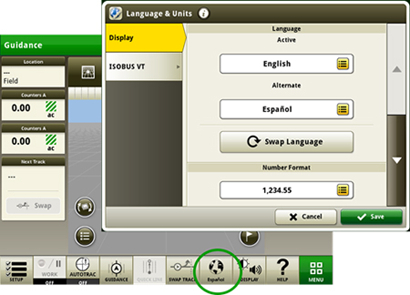 Switch between active and alternate language on the display
Easily switch between languages with the option to set the active and alternate language. Configure the shortcut bar to include the language toggle allows different individuals to easily switch the display between languages.
Machine monitor
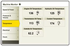 Machine monitor page
- The Machine Monitor application provides you instantaneous readings about the status or condition of your machine.
- This application shows parameters such as engine speed, coolant temperature, and ground speed.
Work monitor
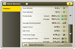 Work monitor page
- The Work Monitor application displays performance information about the task being performed by the machine.
- You are shown averages, totals, and productivity of the machine, such as area worked, average working speed, and fuel usage.
- Work setup places the settings needed to properly setup features such as AutoTrac, Documentation, and Section Control in a single location. Settings include:
- Client, farm, and field
- Crop type
- Machine and implement dimensions
- Variety/hybrid and planting/seeding rates
- Variable rate prescriptions
- Product and application rates
- Application rates through the implement screens
Video looping supported with Gen 4 4600 CommandCenter Display and 4640 Universal Display
- This feature enables users to scan or loop through all of the available video feeds for a specified duration. The default scan time is set to 7 seconds per image. The scan time is customizable per image allowing for consistent visibility to all video feeds.
Flags
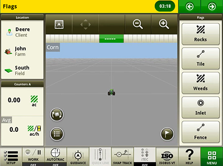 Create flags to mark items in the field
- Mark areas in the field that need special attention such as rocks, tile lines, or weed pressure.
- Flags previously recorded on the Gen 4 or GreenStar™ 3 2630 Display can be transferred between monitors.
- Flags previously recorded on the Gen 4 or GreenStar™ 3 2630 Display can be transferred between monitors.
Automatic base station switching
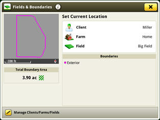
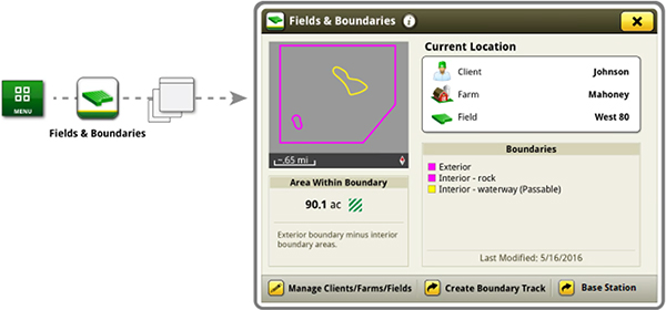 Setup base stations in Fields and Boundaries applications
- Customers using John Deere RTK Radio 450 or 900 can link a base station to a desired client,/ farm,/ or field. This allows automatic switching to the associated base station when changing fields. The ability to import base station assignments into Operations Center and send back to machines will be available at a later date.
Dual-display mode
 Dual display
- Generation 4 CommandCenter may be configured to run with the following John Deere displays connected at the cornerpost of a John Deere tractor:
- GreenStar 2 1800 Display
- GreenStar 2 2600 Display
- GreenStar 3 2630 Display
- 4640 Universal Display
- 4240 Universal Display
NOTE: Vehicle applications will always be located on the Gen 4 CommandCenter.
Video capability
- Machines equipped with a 4200 CommandCenter are equipped with one video input, and the 4600 CommandCenter has four video inputs.
- You have the ability to set a variety of triggers. With each trigger, the image will then appear on the display.
Field boundaries
 Boundary creation from coverage
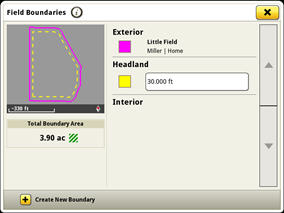 Headland creation
- Manually drive field boundaries with the Generation 4 CommandCenter or import existing boundary information from the GreenStar 3 2630 Display or John Deere Operations Center. Gen 4 documentation data can be used to create boundaries from coverage within the John Deere Operations Center.
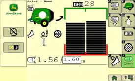
ISOBUS and tractor-baler automation offer new baling experience
Tractor-Baler Automation simplifies baling experience
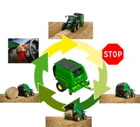 A single manual action; system manages the rest
 TBA awards
The optional Tractor-Baler Automation (TBA) makes baling easy. This exclusive system manages most of the baling process and gives the customer the following advantages:
- High baling comfort a single action to bale instead of four.
- Error proof baling - even after 10 working hours, the system does not forget any action; a true advantage for an inexperienced driver.
- Constant bale quality - same diameter bale after bale
- Constant productivity - no reduced efficiency due to operators fatigue.
When used with a John Deere ISOBUS tractor, electric selective control valve (E-SCV), and (IVT™) transmission, the system will be able to:
- Stop the tractor when bale size is reached
- Wrap the bale
- Open the gate
- Close the gate when bale is unloaded
The only action remaining is to forward reverser and manage the steering.
If the John Deere tractor is not equipped with IVT but has E-SCV and ISOBUS, opening and closing can be automated.
A single touch on SCV, brakes, or reverser will disengage the automation. In the same way, automated open/close can be momentarily stopped when unloading in hilly conditions.
Tractor-Implement Automation is an exclusive green on green advantage. This advanced technology option has won awards at SIMA and Agritechnica farm equipment show in Europe, a true cost/value guarantee.
NOTE: to run through fully automated mode, a John Deere Isobus tractor with E-SCV and IVT is required. A baler activation key and a tractor activation key (different) have to be ordered.
ISOBUS certified balers
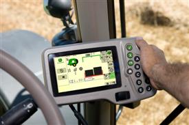
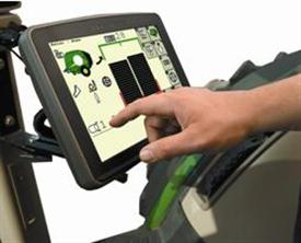
 Plug in and bale with ISOBUS
 ISOBUS certified = compatibility guarantee
The 990 and 960 Balers offer ISOBUS compatibility as base equipment. This standardized communication not only allows the use of John Deere Greenstar2 1800, 2600, or 2630 Displays, but also the use of other ISOBUS conform competitive monitors.
Adapter harnesses for non-ISOBUS tractors are available.
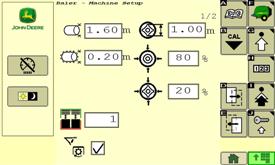
User friendly interface
 Main page with simple and clear pictograms
 Bale or soft core density adjustments
The Baler interface displays information that is needed. The 900 Series monitors provide all required information:
- Bale shape and diameter
- Drop floor and knives position
- Variable core activation
- Tying process status
- Gate position
- Maintenance status
Adjustments can also be managed from the operators station:
- Bale size and density
- Variable core diameter and density
- Net and twine tying parameters
- Knife selection
- Automated lubrication
- Tractor-Baler Automation status
- Bale counter resets
Greenstar™2 1800 has the ideal display for baling application
 Greenstar2 1800 Display ordered with the baler
The 900 Series Balers can be teamed with all ISOBUS certified displays. The Greenstar2 1800 monitor can be ordered with the baler to match traditional baling requirements. When not baling this display can be used for other functions such as guidance and spraying applications when connected to an appropriate receiver and implement.
All ISOBUS display will fit the 900 Series
 GreenStar3 2630 fits the most demanding user needs
The 960 and 990 Balers can be ordered without a monitor for customers who already have an ISOBUS display, or for those who search more advanced application (field management). Displays other than John Deere Greenstar2 1800 can be purchased through Ag Management Solutions (AMS) pages.
Specifications
Specifications
Add Model
Specifications |
||||
|---|---|---|---|---|
| Select up to 4 models to compare specifications | John Deere 7250R Tractor |
Key Specs
| Engine description | John Deere PowerTechPSS (B20 Diesel Compatible) 6.8L | |||
|---|---|---|---|---|
| Engine displacement | 6.8 L 415 cu in. |
|||
| Rated engine power | At 2100 engine rpm: 184 kW 250 hp |
|||
| Rated PTO power (hp SAE) | At 2100 engine rpm: 152 kW 205 hp |
|||
| Transmission type | Standard: John Deere e23™ 42 km/h 26 mph John Deere e23™ Transmission 50 K 31 mph John Deere Infinitely Variable Transmission (IVT) 0.050-42 km/h (0.030-26 mph) John Deere Infinitely Variable Transmission (IVT) 0.050-50 km/h (0.030- 31 mph) |
|||
| Hydraulic pump rated output | Standard: 63 cc: 162 L/min 43 gpm Optional: 85 cc: 222.3 L/min 59 gpm |
|||
| Rear hitch category (SAE designation) | Standard: Category 3/3N with Quik-Coupler Optional: Category 3/3N with Hook Ends Category 3N/3 with Hook Ends |
|||
| Base machine weight | 11,674 kg 25,738 lb |
|||
| Maximum PTO power | ||||
| Maximum engine power |
Engine specifications
| Description | John Deere PowerTechPSS (B20 Diesel Compatible) 6.8L | |||
|---|---|---|---|---|
| Engine type | Diesel, in-line, 6-cylinder, wet-sleeve cylinder liners with 4 valves-in-head | |||
| Engine family | JJDXL06.8309 | |||
| Rated speed | 2100 rpm | |||
| Aspiration | Dual turbochargers, variable geometry turbo with fixed geometry turbo in series | |||
| Cylinders liners | ||||
| Emission level | Final Tier 4 | |||
| After treatment type | DOC/DPF | |||
| Displacement | 6.8 L 415 cu in. |
Engine performance
| Rated power | At 2100 engine rpm: 184 kW 250 hp |
|||
|---|---|---|---|---|
| Rated PTO power (hp SAE) | At 2100 engine rpm: 152 kW 205 hp |
|||
| Power boost | 22 kW 30 hp |
|||
| Engine peak torque | At 1600 rpm: 1171 Nm 864 lb-ft |
|||
| PTO torque rise | 40 percent | |||
| Intelligent Power Management (available in transport and/or mobile PTO applications) | ||||
| Maximum PTO power | ||||
| Maximum engine power |
Transmission
| Type | Standard: John Deere e23™ 42 km/h 26 mph John Deere e23™ Transmission 50 K 31 mph John Deere Infinitely Variable Transmission (IVT) 0.050-42 km/h (0.030-26 mph) John Deere Infinitely Variable Transmission (IVT) 0.050-50 km/h (0.030- 31 mph) |
|||
|---|---|---|---|---|
| Reverser | ||||
| Clutch; wet/dry | ||||
| Creeper |
Hydraulic system
| Type | Closed-center, pressure/flow compensated | |||
|---|---|---|---|---|
| Pump rated output | Standard: 63 cc: 162 L/min 43 gpm Optional: 85 cc: 222.3 L/min 59 gpm |
|||
| Available flow at a single rear SCV | 132 L/min 35 gpm |
|||
| Available flow at front SCVs | 126 L/min 33 gpm |
|||
| Number of rear selective control valves (SCVs) | Standard: 4 SCVs Optional: 1/2 in. ISO Couplers: 3-6 0.75 in. and 0.5 in. ISO couplers: 5 (SCV 1: 0.75 in couplers, SCV 2-5: 0.5 in coupler) |
|||
| Number of mid selective control valves (SCVs) | ||||
| Number of front selective control valves (SCVs) | 1 with front hitch | |||
| Joystick SCV control | ||||
| SCV control | Electronic |
Rear hitch
| Hitch draft control load sense type | ||||
|---|---|---|---|---|
| Remote control valves available | ||||
| Hitch category (SAE designation) | Standard: Category 3/3N with Quik-Coupler Optional: Category 3/3N with Hook Ends Category 3N/3 with Hook Ends |
|||
| Maximum lift capacity behind lift points | Standard (Category 3): 5984 kg 15,200 lb Optional (Category 3N): 7847 kg 17,300 lb Standard (Category 3 with Hook Ends): 6894 kg Optional (Category 3 with Hook Ends): 7847 kg |
|||
| Sensing type | Electrohydraulic | |||
| Rear axle differential lock | ||||
| Lift capacity at standard frame |
Drawbar
| Drawbar category | Standard: Category 3 Optional: Category 3 with heavy duty support |
|||
|---|---|---|---|---|
| Maximum vertical load | Standard: Category 3: 1837 kg 4050 lb Optional: Category 3 with heavy duty support: 4536 kg 10,000 lb |
Rear power take-off (PTO)
| Type | Independent Standard: 44.45 mm (1.75 in.) 20-spline, 1,000 rpm Optional: 44.45 mm (1.75 in.), 20-spline, 1,000 rpm capable of 35 mm (1.375 in.) 540/1000 rpm 44.45 mm (1.75 in.) 20-spline, 1,000 rpm with 1.375 in. 540E/1000/1000E rpm gearcase 44.45 mm (1.75 in.) 20-spline, 1,000 rpm with 1.375 in. 540/540E/1000 rpm gearcase |
|||
|---|---|---|---|---|
| Engine rpm (at rated PTO speeds) | 540/1000 PTO rpm at 1950 engine rpm 540E/1000E PTO rpm at 1750 engine rpm |
|||
| PTO actuation | ||||
| Ground speed PTO option availability | ||||
| Multispeed PTO option availability |
Front hitch
| Category | Category 3N, ground engaging | |||
|---|---|---|---|---|
| Electric power | 7-pin connector | |||
| Standard lift capacity | 5,200 kg 11,464 lb |
|||
| Front power take-off (PTO) | Available Optional: 44.45 mm (1.75 in.), 20 spline, 1,000 rpm, counter-clockwise rotation (when facing PTO) 35 mm (1.375 in.) 21 spline, 1,000 rpm, counter-clockwise rotation (when facing PTO) 35 mm (1.375 in.) 6 spline, 1,000 rpm, counter-clockwise rotation (when facing PTO)** |
|||
| PTO speed | 1,000 PTO rpm at 1940 engine rpm |
Rear axle
| Type | Standard: Rack-and-pinion or flange axles Optional: Diameter: 110 x 2550 mm 4.33 x 100.4 in. Diameter: 110 x 3010 mm 4.33 x 118.5 in. Diameter: 120 x 2550 mm 4.72 x 100.4 in. Diameter: 120 x 3010 mm 4.72 x 118.5 in. 335 mm (13.2 in.) Flanged Axle |
|||
|---|---|---|---|---|
| Final drive type | Inboard planetary three pinion | |||
| Differential controls | ||||
| Axle type | ||||
| Brakes, type and control | ||||
| Rear differential lock | Full-locking electrohydraulic | |||
| Load rating |
Front axle
| Type | Standard: 1300 Series MFWD: tread range 1524 to 2235 mm 60 - 88 in. Optional: TLS: Tread range 1524 to 2235 mm TLS with front brakes, available with 40 kph, standard with 50 kph |
|||
|---|---|---|---|---|
| Front axle differential lock | 1300 Series MFWD: Limited Slip TLS: Limited Slip TLS with front brakes: Full-locking electrohydraulic (actuated at same time as rear diff lock) |
|||
| Load rating |
Tires
| Front | RCI Group 42/43/44 | |||
|---|---|---|---|---|
| Rear | RCI Group 47/48/49 | |||
| Wheel tread range | ||||
| Turning radius with brakes | 380/85R34 group 42 tires at 60 in. spacing 1300: 7 m 23 ft 600/70R30 group 43 tires at 74.1 in. spacing TLS: 6.7 m 22 ft 620/75R30 group 44 tires at 82 in. spacing, TLS: 8.7 m 28.5 ft |
|||
| Turning radius without brakes |
Steering
| Type | Standard: Hydrostatic power Optional: ActiveCommand™ Steering with electric pump back-up |
|---|
Electrical system
| Alternator size | Standard: 200 amp Optional: 240 amp |
|||
|---|---|---|---|---|
| Battery options | 12 V | |||
| Total cold cranking amps | With 2-925 CCA group 31 batteries: 1850 CCA | |||
| Type of bulb in beacon (Halogen, Zenon, LED) | ||||
| Type of bulb in headlight (Halogen, Zenon, LED) | ||||
| Working lights | ||||
| dB(A) rating for backup alarm |
Operator station
| Rollover protective structure, OOS | ||||
|---|---|---|---|---|
| Seat | Standard: ComfortCommand™ Optional: ActiveSeat™ |
|||
| Cab suspension | Optional: Adaptive Hydropneumatic Cab Suspension Plus (Adaptive HCS Plus) | |||
| Instructional seat | Standard | |||
| Display | 10-in. CommandCenter Display with 4600 processor | |||
| Radio | Standard: AM/FM stereo with weatherband, remote controls, auxiliary input jack, four speakers and external antenna Optional; Premium: AM/FM stereo with premium tuner, weatherband, remote controls, USB port and auxiliary input jack , BlueTooth capable including microphone, four speakers, subwoofer, and external antenna |
|||
| Inner cab volume | 3.597 m3 127 cu ft |
|||
| dB(A) rating | ||||
| Cab glass area | 6.52 m2 70.18 sq ft |
|||
| Front visibility | ||||
| Safety glass rating |
Dimensions
| Wheelbase | 2925 mm 115.2 in. |
|||
|---|---|---|---|---|
| Overall length | 5540 mm 218 in. |
|||
| Drawbar clearance | Group 47 rear tires: 360 mm 14.2 in. Group 48 rear tires: 415 mm 16.3 in. Group 49 rear tires: 461 mm 18.1 in. |
|||
| Front axle center | ||||
| Approximate shipping weight, Open;Cab | ||||
| Overall height |
Weight
| Base machine weight | 11,674 kg 25,738 lb |
|||
|---|---|---|---|---|
| Maximum ballast level | SAE PTO hp: 145 lb | |||
| Maximum permissible weight |
Capacities
| Crankcase oil volume | 26 L 27.4 U.S. gal. |
|||
|---|---|---|---|---|
| Fuel tank | e23 (G47/48): 465 L 123 U.S. gal. e23 (G49): 488 L 129 U.S. gal. IVT (G47/48): 520 L 137 U.S. gal. IVT (G49): 543 L 143 U.S. gal. |
|||
| Diesel exhaust fluid (DEF) tank | 23 L 6 U.S. gal. |
|||
| Cooling system | 39.5 L 41.75 qt |
|||
| Transmission-hydraulic system | 160 L 42.3 U.S. gal. |
Serviceability
| Interval for engine oil change | 500 hours | |||
|---|---|---|---|---|
| Interval for hydraulic/transmission oil change | 1,500 hours | |||
| Interval for engine coolant change | 6,000 hours |
Loaders
| Loader | H480 | |||
|---|---|---|---|---|
| Lift capacity at full height | 2411 kg 5315 lb |
|||
| Maximum lift height | 4704 mm 185.2 in. |
Precision AG
| Guidance | AutoTrac Ready | |||
|---|---|---|---|---|
| Telematic | JDLink | |||
| Remote diagnostics | ServiceADVISOR remote: available with JDLink™ hardware and activations Remote Display Access: available with JDLink™ hardware and activations |
Miscellaneous
| Country of manufacture | USA | |||
|---|---|---|---|---|
| Side slope rating | ||||
| Uphill/downhill slope rating |
Additional information
| Date collected |
|---|
Tracks
| Drive type | ||||
|---|---|---|---|---|
| Midrollers | ||||
| Track width | ||||
| Tread spacing |
Accessories and Attachments
Ag Management Solutions
GreenStar/Gen4 - 254 mm (10 in.) Display Touch Panel Protector Service Kit - PF90596
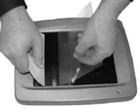
This product is similar to the protective film used on hand-held touchscreen electronics and can reduce screen damage from regular use. It includes all necessary instructions and tools to install the transparent film over a touchscreen display.
Harness - Original GreenStar Display and Mobile Processor to GreenStar 3 or GreenStar 2 (Round) Cornerpost - PF90686
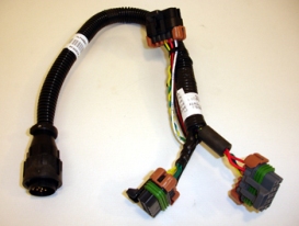 GreenStar 2 vehicle connector
Beacon Lighting
Rotary Beacon Light Kit, Left Side - RE334623
The rotary beacon light is installed to meet requirements in commercial or governmental applications. The rotating, high-intensity light rests securely within an amber-colored safety lens. Both the light and lens are replaceable if damaged.
The rotary beacon light features a fully adjustable, double-clamp design that provides a more rigid vertical support stem.
Rotary Beacon Light Kit, Right Side - BRE10043
The rotary beacon light is installed to meet requirements in commercial or governmental applications. The rotating, high-intensity light rests securely within an amber-colored safety lens. Both the light and lens are replaceable if damaged.
The rotary beacon light features a fully adjustable, double-clamp design that provides a more rigid vertical support stem.
Cab Equipment
Step Mud Guard, Left Side - BRE10127
The left-hand step mud guard is intended for use with the full-coverage rear fender. The left-hand step mud guard is provided with G49 rear tires.
Cab Operator's Station
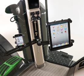
Accessory Mounting Bracket - RE343680
Cell phones, tablets, and other devices are key tools for farming today. John Deere has now made it easier than ever to incorporate these tools into the operator's station.
Stay connected with the RAM® cell phone and tablet mounts. John Deere offers a vast selection of adjustable accessory mounting solutions and media devices to fit every need and application.
 Mounting bracket with cell phone and tablet mount
 Mounting bracket with cell phone and tablet mount
RAM is a trademark of National Products Inc.
Cell Phone Mount Kit - BRE10015
Cell phones, tablets, and other devices are key tools for farming today. John Deere has now made it easier than ever to incorporate these tools into the operator's station.
Stay connected with the RAM® cell phone and tablet mounts. John Deere offers a vast selection of adjustable accessory mounting solutions and media devices to fit every need and application.
Mounting bracket with cell phone and tablet mount
Mounting bracket with cell phone and tablet mount
RAM is a trademark of National Products Inc.
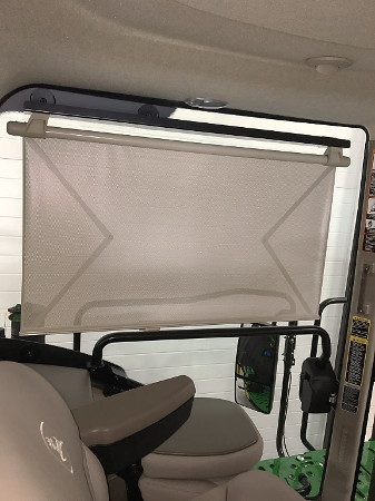
Left side window shade bracket kit - BRE10472
Block distractions out of the left side window of select tractor and sprayer cabs. The left-side sun shade bracket allows producers to mount their choice of two different sized sun shades to the cab door. The shade system design allows operators to block light and heat from the sun while not obstructing the cab entrance and exit access. The bracket kit is compatible with existing sun shades for a matched look in the cab with quality and features users are already comfortable with.
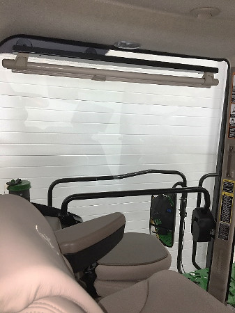 Bracket shown with large sun shade retracted on 8RT
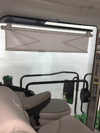 Sun shade 30 percent open on 8RT
 Sun shade 95 percent open on 8RT
- Block light from the sun and from high-intensity work lights at night
- Reduce summer heat from direct sun
- Sun shade options match the current interior (also orderable)
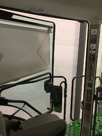 Bracket shown with large sun shade at 95 percent open on 8RT with door open
Power Strip with Six Outlets - RE68495
Power strip and accessories
 Power strip kit
 Power strip installed
The power strip provides six additional electrical outlets that give either permanent or ignition-key-controlled power for such items as:
-
Computers
-
Portable telephone chargers
-
Implement monitor
-
Implement supply
-
12-V and up to 30-amp total current can be taken from these outlets
The power strip is not a surge suppressor. Electrical equipment with program memory or capacity for data storage requires protection from the damage of electrical surges and spikes that could occur in systems without transient voltage protection.
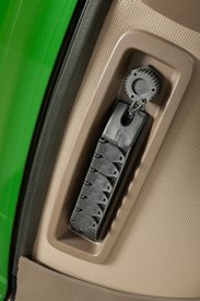
Self - Leveling Cup Holder - BRE10152
A favorite worldwide, the RAM self-leveling cup holder is now available as a kit - designed specifically for Deere equipment. It is easily installed to keep your favorite beverage upright even in the roughest terrain. The perfect accessory for any cab that has 10-mm mounting bosses.
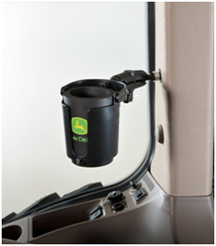 Self-leveling cup holder John Deere branded beverage insulator included
The new cup holder features a unique self-leveling design. This pivoting design allows easy adjustment for the holder while offsetting motion of the vehicle when moving.
Features and applications:
- Self-leveling action reduces spills
- Durable design for rough environments
- Easy adjustable mounting for ideal placement
- Includes John Deere branded beverage insulator
- Compatible with most monitor brackets and all 10-mm threaded bosses
Storage Container with Lid/Ash Tray - RE275532

This ashtray fits into the existing console cup holder.
Commandview Iii Cab
Single Lever Multi Function Joystick - BRE10143

This optional cross-gate joystick replaces fingertip paddle pots for control of selective control valves (SCVs) and allows for programmable hydraulic functionality according to operator preference.
Drawbar
Drawbar
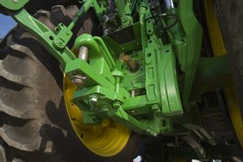
Drawbar, Category 3 Clevis (Heavy Duty) - BRE10211
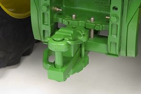 Category 3 drawbar with clevis with pin
 Category 3 drawbar with clevis with pin
High vertical load drawbar improves tractor versatility by being compatible with implements with high hitch vertical loads.
This Category 3 drawbar option includes a heavy-duty drawbar support with maximum drawbar static vertical load at 4536-kg (10,000 lb) and can be adjusted to 25.4-, 35.6-, and 40.6-cm (10-, 14-, and 16-in.) lengths required by power take-off (PTO) implements. Drawbar pin size is 38-mm (1.5 in.).
Applications:
Medium- to heavy-sized 3-point-hitch implements, such as row-crop cultivators, and typical- to heavy-sized drawn field implements such as a field cultivator, chisel plow, or loaded grain carts.
Electrical Equipment
9-Pin Connector Implement Feedback - RE58827
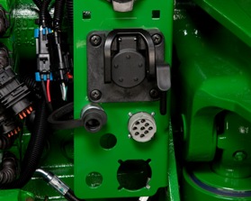 9-pin electrical connector
The 9-pin electrical connector is required to allow TouchSet depth control to be used with implements with this feature. The harness provides a position input to the tractor selective control valve unit enabling the TouchSet system.
This feature allows the operator to adjust height and depth of remote lift cylinders by using the TouchSet controls in the cab.
Battery Disconnect Switch - BRE10077
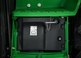 Battery disconnect installed
Available as either a factory- or field-installed attachment, the battery disconnect switch is used to disconnect the batteries in preparation for 20-day to 90-day storage periods. The switch cuts the power to the entire tractor to aid in maintaining battery life.
An indicator light allows for safe and proper disconnect. The light will flash until it is safe to disconnect. This allows the diesel exhaust fluid (DEF) tank and lines to purge. (Final Tier 4 has an indicator light and Interim Tier 4 has no indicator light.)
Cummins is a trademark of Cummins Incorporated.
Heater, Cold Weather Auxiliary Package, 110V, 6.8L AQ/CQ/IVT/PST - BRE10178
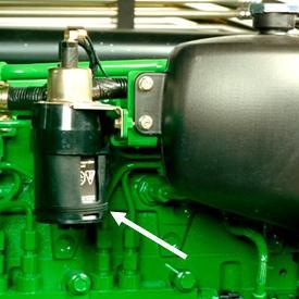 Ether valve and canister
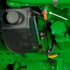 Block heater
The optional cold start package is recommended for tractors frequently started at or below -6°C (21.2°F).
The kit includes factory-installed activation switch and ether valve with ether canister. A 120-V, high-wattage block heater and grounded cord are also included with the factory-installed option.
High Capacity 240 amp Alternator - RE550906
All model years of R4030, R4038, R4044, R4045, and R4060 Sprayers can be upgraded to include ExactApply intelligent nozzle control. The ExactApply performance upgrade kits are compatible with steel and carbon fiber booms. Additionally, the sprayer needs stainless-steel plumbing and nozzle spacing of 38 cm or 51 cm (15 in. or 20 in.).
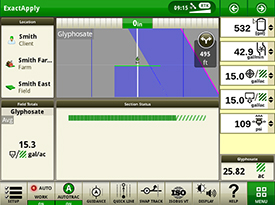 ExactApply on 4640 Universal Display
ExactApply performance upgrade kits are compatible with the GreenStar™ 3 2630 Display, the 4600 CommandCenter™ Display, and the 4640 Universal Display.
Setup time
| Boom width | Boom type | Time |
| 27.4 m (90 ft) | Steel | 20 hours |
| 30.5 m (100 ft) | Steel | 22 hours |
| 36.6 m (120 ft) | Steel | 24 hours |
| 36.6 m (120 ft) | Carbon fiber | 19 hours |
| 40.2 m (132 ft) | Carbon fiber | 21 hours |
How to order
Four part numbers need to be ordered to complete an ExactApply performance upgrade kit. Kits are customized based on the sprayer’s chassis, boom, alternator, and display.
Step 1: Select a chassis kit.
| Model | Configuration | Kit |
| R4030 | Poly tank | BKK10805 |
| Stainless-steel tank | BKK10806 | |
R4038 R4044 |
Stainless-steel tank | BKK10806 |
R4045 R4060 |
Stainless-steel tank | BKK10806 |
Step 2: Select a boom kit.
| Model | Configuration | Kit |
R4030 |
27.4-m (90-ft) steel boom with 38-cm (15-in.) spacing | BKK10807 |
| 27.4-m (90-ft) steel boom with 51-cm (20-in.) spacing | BKK10808 | |
| 30.5-m (100-ft) steel boom with 38-cm (15-in.) spacing | BKK10809 | |
| 30.5-m (100-ft) steel boom with 51-cm (20-in.) spacing | BKK10810 | |
| 36.6-m (120-ft) steel boom with 38-cm (15-in.) spacing | BKK10811 | |
| 36.6-m (120-ft) steel boom with 51-cm (20-in.) spacing | BKK10812 | |
| 36.6-m (120-ft) carbon fiber boom with 38-cm (15-in.) spacing | BKK11125 | |
| 36.6-m (120-ft) carbon fiber boom with 51-cm (20-in.) spacing | BKK11124 | |
| 40.2-m (132-ft) carbon fiber boom with 38-cm (15-in.) spacing | BKK11123 | |
| 40.2-m (132-ft) carbon fiber boom with 51-cm (20-in.) spacing | BKK11122 |
Step 3: Select an alternator kit.
| Model | Configuration | Kit |
| R4030 | Alternator for 6.8 L (415-cu in.) engine | AKK18421 |
R4038 |
Alternator for 9.0 L (549-cu in.) Final Tier 4 (FT4) engine | RE550906 |
Step 4: Select a display kit.
NOTE: This kit includes the software and operator's manual. An additional display does not need to be purchased.
| Model | Configuration | Kit |
R4030 |
Software and manual kit, GreenStar 3 2630 Display and 4640 Universal Display – US | BKK10813 |
| Software and manual kit, GreenStar 3 2630 Display and 4640 Universal Display – Canada | BKK10814 | |
| Software and manual kit, Gen 4 display – US | BKK10815 | |
| Software and manual kit, Gen 4 display – Canada | BKK10816 |
ISO Cab Implement CAN bus Adapter - RE322780
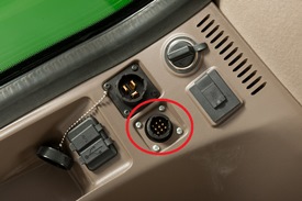 ISO 11783 location in R-Series Tractor cab
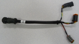 RE322780 ISO cab implement CAN bus adapter
The ISO cab implement controller area network (CAN) bus adapter is available to connect any ISO compliant implement or device to an 8R, 8RT, 9R, 9RT, 9RX (including Scraper Special) Series Tractor. These connectors are commonly used for planter frame control boxes.
Refer to the operator's manual, sections 16 (CommandCenter™) and 25 (Operator Station), for additional information on ISO implements.
NOTE: If the harness is not in use, unplug it from the ISO 11783 location or plug the 4-pin connectors together on the harness. If neither of these are done, implement CAN communication errors will occur.
Implement Switch with 3 m (10 ft) Harness - RE21519
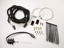 Implement switch
The implement switch indicates to the CommandCenter™ system when the implement is raised or lowered, providing accurate data collection when using a performance monitor.
Radar with Dual Beam Sensor - NA - RE278980
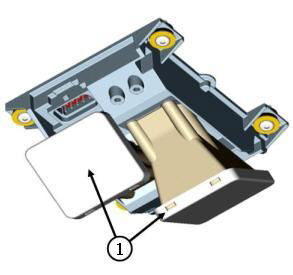 Dual-beam radar emission horns
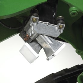 Dual-beam radar (tracks tractor shown)
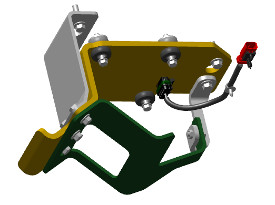 Shield for dual radar beam
In today’s agricultural environment, accuracy and precision are more important than ever. For something as basic as ground speed, operators need key information for precise control of various implements and the tractor. To support these needs, tractors can be ordered with a dual-beam radar unit as a factory- or field-installed option.
There are several key features that have changed from previous designs.
First, there are two horns for exit of the radio beam. This dual-beam design assures a powerful and accurate signal that will cut through interference that at times makes single-beam units inaccurate (see 1 in the image above for beam locations). Dual-beam output makes radar less susceptible to hard surface or tall/wavy grass interference.
Accuracy is aided by a heavy-gauge mounting bracket and rubber isolators that reduce chances that vibration can affect the radio signal.
Dual-beam radar has a fast update rate. When the tractor comes to a stop, accelerates, or varies speed, the indicated ground speed on the tractor display will closely match the actual ground speed. This is important for implements that use radar speed to control operation such as planters, seeders, fertilizer applicators, and sprayers.
In addition, the dual-beam radar does not require calibration to assure accuracy. Its self-calibrating ability is sure to save setup time by elimination of a special procedure that was required in the past.
The radar true ground speed sensor activates the following CommandCenter™ display or performance monitor readouts:
- Percent slip
- Hitch slip command (if equipped)
Radar usage improves the accuracy of the following CommandCenter display or performance monitor functions:
- Area covered
- Area/hour
- Distance and ground speed
Dual-beam units are compatible with controller area network (CAN) bus and International Organization for Standardization (ISO) bus electrical systems.
Engine
Intelligent Power Management - RE298885
IPM
NOTE: IPM is only available for Final Tier 4 (FT4)/Stage V engines, and not for Stage II and Tier 3/Stage IIIA engines.
This feature is for many typical farming operations that use the rear power take-off (PTO) in high-power applications or the tractor as a transport vehicle. Operators who are looking for more power in non-stationary PTO and transport applications will be interested in the IPM feature.
In high rear PTO power applications such as forage harvesters, rototillers, and beet or potato harvesting equipment or where heavy trailers, carts, or implements are moved to and from various locations, this feature provides significant additional capabilities. The solution improves productivity with more consistent ground speeds, quicker acceleration, and the ability to better hold desired transport speeds.
This two-in-one tractor solution successfully operates in power-intensive PTO and transport applications without being disadvantaged by the extra costs of the next higher horsepower model.
This feature is available as a factory- or field-installed option.
Tractor applications
 8R Tractor in transport
Rear PTO field applications
- Rear-mounted snow blowers
- Sugar beet harvesting
- Forage harvesters
- Potato harvesting
- Rotary cutters
- Mower conditioners
- Flail mowers
- Balers
- Soil stabilizing
- Power harrow
- Vegetable bed formers
- Muck spreaders
Transport applications
- Grain carts or wagons
- Slurry tanks
- Implement transport from field to field
- Pull-type sprayers
- Extensive operation in hills/roadways
This is not intended to be an inclusive list of all applications but shows the wide range of uses for additional engine horsepower.
Power available
IPM provides a controlled power boost of up to 26 engine kW (35 engine hp) to the tractor under the following operating conditions:
- Tractor moving and PTO under load
- Transport during acceleration
Power increase is not provided under draft applications or non-moving rear PTO applications.
How it works
There are specific operating parameters when IPM functions to boost engine power. It is the "intelligent" part of the system that provides seamless operation while adjusting the engine horsepower limits depending on how the tractor is being used. For engine horsepower boost activation, the tractor must be running an application that is using the full power capability of the tractor.
PTO activation
Power must be sensed going through the PTO by the tractor's electronic systems. The tractor must be moving at least 0.5 km/h (0.3 mph) and PTO consuming moderate power before power boost is enabled.
NOTE: If the tractor is equipped with a front PTO, additional IPM power may transfer through the front PTO. However, IPM activation is only sensed through the rear PTO. Adequate load must be sensed on the rear PTO for IPM to activate (non-transport work).
Transport activation
When in transport applications, power transition is smooth. The engine will respond seamlessly as load changes, such as when going up and down hills. Additional power is available at a useful transport speed with minor differences between tractor models and transmissions.
The minimum ground speed is where additional power will begin to be applied, assuming the engine is already fully loaded. Ramp up to full additional power occurs as speed continues to increase. Full additional power occurs within a 3 mph (5 km/h) band.
Transport during acceleration: power boost increases from 23 km/h – 28 km/h (14.3 mph – 17.4 mph).
Transport during deceleration: power boost decrease from 23 km/h – 18 km/h (14.3 mph – 11.2 mph).
Power boost levels other than at rated rpm
Power boost is a function of engine speed per the following example:
 Usable rpm range of operation (8R 370 shown)
IPM (shown in red in chart above versus standard power shown in blue) provides additional engine horsepower from rated engine speed down to 1600 rpm, which is peak engine torque.
Operator visibility and control of operation
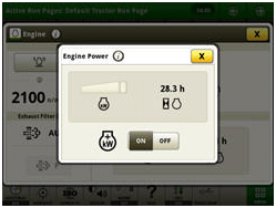 Engine power display
All tractors have the power meter display function as base equipment. The operator can observe when full capabilities of the tractor are being utilized. This function graphically displays power utilization up to rated horsepower and power bulge.
The power meter can be found in the CommandCenter™ display. If the engine is off or has minimal load, the power meter will not fill in. The meter is similar in concept to a cellular phone's signal-strength meter. As the power increases, it will fill in bars in an icon. The display will also show the level of additional power being used. The long section represents up to the rated power. The smaller section represents power bulge and is an indicator of additional power available with IPM.
Via the CommandCenter, there is also the ability to enable or disable the function. The Operator's Manual provides simple details about navigating the engine screen.
If equipped with this option, IPM is automatically enabled each time the tractor is started. IPM can be turned off through the CommandCenter display.
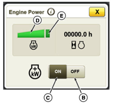 IPM settings in CommandCenter display include Power Management off toggle (B) and Power Management on toggle (C)
Tractor compatibility with additional power
IPM has been thoroughly tested by John Deere engineers to be compatible with the base tractor equipment with no impact to reliability. John Deere provides IPM. Unapproved aftermarket devices that boost power without regard to engine, transmission, axles, and drawbar, or hitch capability.
This feature provides optimal utilization of tractor components. For example, with moving PTO operation, power splits through axles to move the tractor along the ground and turn the PTO shaft and implement. Adding power to this combined system does not overload either one individually. At transport speeds, axle torque load decreases significantly from levels seen at working field speeds. Adding IPM power at transport does not overload transmissions or axles.
Aftermarket devices are not selective when power increases are available. Great amounts of power increase may be promised with these devices. Large power changes are not compatible with base tractor equipment. The tractor’s systems are specifically designed to ensure durability of the total vehicle as power increases. Operating outside of the design capabilities of the tractor base equipment will have an impact on durability and reliability.
Fenders
Fender, Rear Extensions - 2.55 m (100 In.) Width - RE318606
Full-coverage fenders
Rear fenders are designed to provide optimum mud control by increasing the coverage of the rear tires in all directions. Two rear fender extension options are offered to provide overall width coverage of 2.55 m (100 in.) or 2.75 m (108 in.). Additionally, fender extension options are available to further increase coverage.
Most importantly, the fender increases the coverage over the rear of the tire, decreasing the amount of mud or debris buildup on the cab's windows, selective control valve (SCV) stack, hitch, and drawbar.
Rear fenders are available as factory-installed or as a field-installed attachment.
Rear fenders are also available as Accessories.
Fenders, Pivoting Front - 710mm (27.9 In) Wide - BRE10126
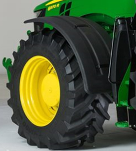
This kit includes the deluxe, pivoting, full-coverage, front fender mounting structure for tractors with a mechanical front-wheel drive (MFWD).
-Protection from mud, stones, and debris when using wide front tires
-Same turning angle as tractors without front fenders.
Producers must also order black plastic fenders (R338473 x2).
Recommended for use with Group 43 or 44 front tires, 600 mm (11.8 in.) or wider.
Front Hitch
Carrier to Ground Engaging, Front Hitch Conversion Kit - RE326580
 7R front hitch ready with front weight support
 7R front hitch ready frame/hydraulic lines
The front hitch/PTO ready option is ideal for any 7 Family Tractor that may be used for future applications requiring a front hitch or PTO. This option is also beneficial for increased resale value as it provides flexibility for future owners.
This option includes a front casting that accommodates, but does not include a front hitch and front PTO.
- With a mechanical front-wheel drive (MFWD) axle, this option includes one set of hydraulic oil lines to connect the front hitch and mid-mount selective control valve (SCV). Mid-mount valves must be purchased separately. Additional hydraulic lines can be field installed allowing up to two front auxiliary couplers with a John Deere field-installed hitch.
- On tractors with a Triple-Link Suspension (TLS™) front axle, the option includes three sets of hydraulic lines to connect the front hitch to the mid-mount SCV and up to two front auxiliary couplers. Mid-mount valves must be purchased separately.
In-cab controls for front PTO and front hitch have to be ordered through Parts when ordering the front PTO and front hitch field-installed options.
Front hitch ready tractors are not shipped with standard front weight support. A front weight support that bolts to the tractor can be ordered as a factory- or field-installed option. The weight support is compatible with suitcase weights (up to 24) and with the 900-kg or 1150-kg (1984-lb or 2535-lb) monster pick-up (monster) weights.
Front weight support is not compatible with front hitch and must be removed before a hitch can be installed.
The sixth rear electrohydraulic SCV is not compatible with front hitch options because of the mid-mount hydraulics for front hitch.
Field-installed hitch options for front hitch/PTO ready tractors:
- Premium (ground-engaging) front hitch with push bar
- Standard (carrier version) front hitch less push bar
Attachments, front-hitch conversion to ground-engaging 5194-kg (11,450-lb) lift capacity
Conversion from carrier version 5194-kg (11,450-lb) lift capacity to ground-engaging 5194-kg (11,450-lb) lift capacity for 7R Series Tractors
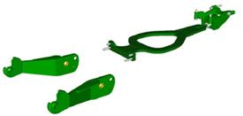 Heavy-duty front hitch
Those who want more productivity out of the 7R Series Tractors with a carrier-version front hitch have the ability to add tillage and other ground-engaging implements with the front-hitch conversion kit. The heavy-duty front hitch is recommended for the most demanding applications. It is designed for extreme stress from pushing hard on tillage implements, very wide implements, severe shock loads, or other heavy-duty applications. Premium hitches are also well suited for mounting three-point blades.
Field-installed kit RE326580 provides a set of heavy-duty lower hitch links, a push bar, and push bar mounting bracket. This hitch is suitable for use under normal conditions including primary tillage equipment or lifting heavy implements. The ground-engaging version is designed for full clearance and does not limit the turning radius at any tread width setting.
The tractor frame includes the mounting points for the push bar, making field conversion possible. Link conversion is possible by removing two pins for each link. Install the push bar with four cap screws in the front, four in the mid-chassis, and tighten two large jam nuts where the push bar attaches to the push bar bracket. There are no ground clearance trade-offs with the addition of the push bar and heavy-duty links. Both versions of the front hitch are entirely compatible with the front power take-off (PTO).
The conversion kit to ground-engaging front hitch adds 117 kg (260 lb) of additional weight to the tractor.
Front Hitch Ready - Add Ground Engaging Hitch - BRE10303
7R front hitch ready with front weight support
7R front hitch ready frame/hydraulic lines
The front hitch/PTO ready option is ideal for any 7 Family Tractor that may be used for future applications requiring a front hitch or PTO. This option is also beneficial for increased resale value as it provides flexibility for future owners.
This option includes a front casting that accommodates, but does not include a front hitch and front PTO.
- With a mechanical front-wheel drive (MFWD) axle, this option includes one set of hydraulic oil lines to connect the front hitch and mid-mount selective control valve (SCV). Mid-mount valves must be purchased separately. Additional hydraulic lines can be field installed allowing up to two front auxiliary couplers with a John Deere field-installed hitch.
- On tractors with a Triple-Link Suspension (TLS™) front axle, the option includes three sets of hydraulic lines to connect the front hitch to the mid-mount SCV and up to two front auxiliary couplers. Mid-mount valves must be purchased separately.
In-cab controls for front PTO and front hitch have to be ordered through Parts when ordering the front PTO and front hitch field-installed options.
Front hitch ready tractors are not shipped with standard front weight support. A front weight support that bolts to the tractor can be ordered as a factory- or field-installed option. The weight support is compatible with suitcase weights (up to 24) and with the 900-kg or 1150-kg (1984-lb or 2535-lb) monster pick-up (monster) weights.
Front weight support is not compatible with front hitch and must be removed before a hitch can be installed.
The sixth rear electrohydraulic SCV is not compatible with front hitch options because of the mid-mount hydraulics for front hitch.
Field-installed hitch options for front hitch/PTO ready tractors:
- Premium (ground-engaging) front hitch with push bar
- Standard (carrier version) front hitch less push bar
Attachments, front-hitch conversion to ground-engaging 5194-kg (11,450-lb) lift capacity
Conversion from carrier version 5194-kg (11,450-lb) lift capacity to ground-engaging 5194-kg (11,450-lb) lift capacity for 7R Series Tractors
Heavy-duty front hitch
Those who want more productivity out of the 7R Series Tractors with a carrier-version front hitch have the ability to add tillage and other ground-engaging implements with the front-hitch conversion kit. The heavy-duty front hitch is recommended for the most demanding applications. It is designed for extreme stress from pushing hard on tillage implements, very wide implements, severe shock loads, or other heavy-duty applications. Premium hitches are also well suited for mounting three-point blades.
Field-installed kit RE326580 provides a set of heavy-duty lower hitch links, a push bar, and push bar mounting bracket. This hitch is suitable for use under normal conditions including primary tillage equipment or lifting heavy implements. The ground-engaging version is designed for full clearance and does not limit the turning radius at any tread width setting.
The tractor frame includes the mounting points for the push bar, making field conversion possible. Link conversion is possible by removing two pins for each link. Install the push bar with four cap screws in the front, four in the mid-chassis, and tighten two large jam nuts where the push bar attaches to the push bar bracket. There are no ground clearance trade-offs with the addition of the push bar and heavy-duty links. Both versions of the front hitch are entirely compatible with the front power take-off (PTO).
The conversion kit to ground-engaging front hitch adds 117 kg (260 lb) of additional weight to the tractor.
Front Hitch Valve (120 ml.) with TLS Axle - RE340779
This attachment provides SCV hydraulic lines from the mid-valve to the front of the machine to control implement functions from the cab.
Front Hitch Valve (120 ml.) without TLS Axle - RE340777
This kit is for adding only the SCVs to tractors that are not front hitch ready from the factory.
The addition of these front SCVs are required for the use of front hydraulically-powered implement accessories such as a hitch, loader, snow blower, or other accessories. Additional kits (such as software, mounting brackets, and joysticks) may be necessary depending on the accessory and functionality desired.
Front Tow Point - R264789
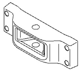
To fulfill the legal requirements of some areas, a front tow point can be field installed on the front base weight. Mounting hardware must be ordered individually.
Second SCV for Front Hitch (120 ml.) - RE340780
This attachment provides SCV hydraulic lines from the mid-valve to the front of the machine to control implement functions from the cab.
Third SCV for Front Hitch (120 ml.) - RE340782
This attachment provides SCV hydraulic lines from the mid-valve to the front of the machine to control implement functions from the cab.
Front Weights
Front Hitch Ready Weight Support - RE326583
7R front hitch ready with front weight support
7R front hitch ready frame/hydraulic lines
The front hitch/PTO ready option is ideal for any 7 Family Tractor that may be used for future applications requiring a front hitch or PTO. This option is also beneficial for increased resale value as it provides flexibility for future owners.
This option includes a front casting that accommodates, but does not include a front hitch and front PTO.
- With a mechanical front-wheel drive (MFWD) axle, this option includes one set of hydraulic oil lines to connect the front hitch and mid-mount selective control valve (SCV). Mid-mount valves must be purchased separately. Additional hydraulic lines can be field installed allowing up to two front auxiliary couplers with a John Deere field-installed hitch.
- On tractors with a Triple-Link Suspension (TLS™) front axle, the option includes three sets of hydraulic lines to connect the front hitch to the mid-mount SCV and up to two front auxiliary couplers. Mid-mount valves must be purchased separately.
In-cab controls for front PTO and front hitch have to be ordered through Parts when ordering the front PTO and front hitch field-installed options.
Front hitch ready tractors are not shipped with standard front weight support. A front weight support that bolts to the tractor can be ordered as a factory- or field-installed option. The weight support is compatible with suitcase weights (up to 24) and with the 900-kg or 1150-kg (1984-lb or 2535-lb) monster pick-up (monster) weights.
Front weight support is not compatible with front hitch and must be removed before a hitch can be installed.
The sixth rear electrohydraulic SCV is not compatible with front hitch options because of the mid-mount hydraulics for front hitch.
Field-installed hitch options for front hitch/PTO ready tractors:
- Premium (ground-engaging) front hitch with push bar
- Standard (carrier version) front hitch less push bar
Attachments, front-hitch conversion to ground-engaging 5194-kg (11,450-lb) lift capacity
Conversion from carrier version 5194-kg (11,450-lb) lift capacity to ground-engaging 5194-kg (11,450-lb) lift capacity for 7R Series Tractors
Heavy-duty front hitch
Those who want more productivity out of the 7R Series Tractors with a carrier-version front hitch have the ability to add tillage and other ground-engaging implements with the front-hitch conversion kit. The heavy-duty front hitch is recommended for the most demanding applications. It is designed for extreme stress from pushing hard on tillage implements, very wide implements, severe shock loads, or other heavy-duty applications. Premium hitches are also well suited for mounting three-point blades.
Field-installed kit RE326580 provides a set of heavy-duty lower hitch links, a push bar, and push bar mounting bracket. This hitch is suitable for use under normal conditions including primary tillage equipment or lifting heavy implements. The ground-engaging version is designed for full clearance and does not limit the turning radius at any tread width setting.
The tractor frame includes the mounting points for the push bar, making field conversion possible. Link conversion is possible by removing two pins for each link. Install the push bar with four cap screws in the front, four in the mid-chassis, and tighten two large jam nuts where the push bar attaches to the push bar bracket. There are no ground clearance trade-offs with the addition of the push bar and heavy-duty links. Both versions of the front hitch are entirely compatible with the front power take-off (PTO).
The conversion kit to ground-engaging front hitch adds 117 kg (260 lb) of additional weight to the tractor.
Pick Up Weight 1500 kg (3307 lb) Monoblock - BL15020
Front weights provide additional ballast for the front axle.
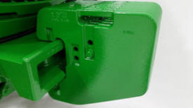 Front support with suitcase weights
Cast Quik-Tatch suitcase weights (R127764) can be added to provide additional ballast for implements that exert heavy draft loads and require additional ballast or with hitch-mounted implements that require additional ballast to maintain steering control while transporting.
These weights are Quik-Tatch weights that require minimal effort to attach.
Pick-up weights
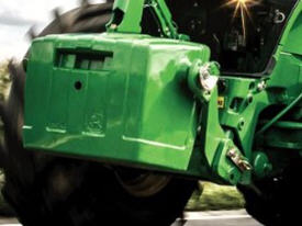 Pick-up weights
Pick-up weights are design to add fast weight to the tractor. Following pick-up weights can be mounted at the front.
Support (base weight):
- Pick-up weight 900 kg
- Pick-up weight 1150 kg
All pick-up hitches can be mounted also at the rear in the 3-point hitch as a counter weight.
To use the third mounting point, an additional center-link bracket is available.
1500 kg and 1800 kg pick-up weights
The two weights differ only internally, therefore no external differences are visible.
The pick-up weights can either be installed on the rear hitch or on the front hitch of the tractor using the center-link bracket. They cannot be mounted directly on the front base weight. A front hitch is required. The center-link bracket for installation is included.
 New pick up weight attached on 6R
The new shape of the 1500 kg and 1800 kg pick-up weights allows a quick and safe mounting.
This is ensured by an optimal alignment of the weight and the tractor along with a self-centering design.
Major benefits of the new design:
- Easy and comfortable
- Less time is required
- Lower risk of injury
Due to the user-friendliness, an optimal ballasting of the tractor is guaranteed at any time.
The performance of the tractor is used to a greater extent, which leads to higher productivity and a reduction in fuel consumption.
 Self-Centering of new pick-up weight
The weights cannot be front installed in combination with Quik-Tatch front weights.
NOTE: Ballast should be limited by the lowest of either tire capacity or tractor capacity. The carrying capacity of each tire should not be exceeded. For more ballasting information refer to the operator's manual and ballast calculator.
Pick Up Weight, 1150 kg (2535 lb) Monoblock - BL15084
Front weights provide additional ballast for the front axle.
Front support with suitcase weights
Cast Quik-Tatch suitcase weights (R127764) can be added to provide additional ballast for implements that exert heavy draft loads and require additional ballast or with hitch-mounted implements that require additional ballast to maintain steering control while transporting.
These weights are Quik-Tatch weights that require minimal effort to attach.
Pick-up weights
Pick-up weights
Pick-up weights are design to add fast weight to the tractor. Following pick-up weights can be mounted at the front.
Support (base weight):
- Pick-up weight 900 kg
- Pick-up weight 1150 kg
All pick-up hitches can be mounted also at the rear in the 3-point hitch as a counter weight.
To use the third mounting point, an additional center-link bracket is available.
1500 kg and 1800 kg pick-up weights
The two weights differ only internally, therefore no external differences are visible.
The pick-up weights can either be installed on the rear hitch or on the front hitch of the tractor using the center-link bracket. They cannot be mounted directly on the front base weight. A front hitch is required. The center-link bracket for installation is included.
New pick up weight attached on 6R
The new shape of the 1500 kg and 1800 kg pick-up weights allows a quick and safe mounting.
This is ensured by an optimal alignment of the weight and the tractor along with a self-centering design.
Major benefits of the new design:
- Easy and comfortable
- Less time is required
- Lower risk of injury
Due to the user-friendliness, an optimal ballasting of the tractor is guaranteed at any time.
The performance of the tractor is used to a greater extent, which leads to higher productivity and a reduction in fuel consumption.
Self-Centering of new pick-up weight
The weights cannot be front installed in combination with Quik-Tatch front weights.
NOTE: Ballast should be limited by the lowest of either tire capacity or tractor capacity. The carrying capacity of each tire should not be exceeded. For more ballasting information refer to the operator's manual and ballast calculator.
Standard Front Weight Support - R288797
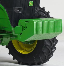 7R front weight support with 24 suitcase weights
Front ballast options are designed specifically for the 7R Series Tractor to provide operators the ability to add Quik-Tatch front weights as needed to correctly ballast the tractor.
The 7R ballast calculator should be used to help determine the correct ballast level for each application.
The front weight support weighs 124 kg (274 lb) and has a 24-weight carrying capacity. Each front suitcase weight weighs approximately 43 kg (95 lb).
NOTE: Front suitcase weights are not compatible with front loaders.
NOTE: Not all ballast option codes are available in all geographic regions. Refer to Price Pages for availability.
Weight, front suitcase 43 kg (95 lb) quantity of one - R127764
Front weights provide additional ballast for the front axle.
Front support with suitcase weights
Cast Quik-Tatch suitcase weights (R127764) can be added to provide additional ballast for implements that exert heavy draft loads and require additional ballast or with hitch-mounted implements that require additional ballast to maintain steering control while transporting.
These weights are Quik-Tatch weights that require minimal effort to attach.
Pick-up weights
Pick-up weights
Pick-up weights are design to add fast weight to the tractor. Following pick-up weights can be mounted at the front.
Support (base weight):
- Pick-up weight 900 kg
- Pick-up weight 1150 kg
All pick-up hitches can be mounted also at the rear in the 3-point hitch as a counter weight.
To use the third mounting point, an additional center-link bracket is available.
1500 kg and 1800 kg pick-up weights
The two weights differ only internally, therefore no external differences are visible.
The pick-up weights can either be installed on the rear hitch or on the front hitch of the tractor using the center-link bracket. They cannot be mounted directly on the front base weight. A front hitch is required. The center-link bracket for installation is included.
New pick up weight attached on 6R
The new shape of the 1500 kg and 1800 kg pick-up weights allows a quick and safe mounting.
This is ensured by an optimal alignment of the weight and the tractor along with a self-centering design.
Major benefits of the new design:
- Easy and comfortable
- Less time is required
- Lower risk of injury
Due to the user-friendliness, an optimal ballasting of the tractor is guaranteed at any time.
The performance of the tractor is used to a greater extent, which leads to higher productivity and a reduction in fuel consumption.
Self-Centering of new pick-up weight
The weights cannot be front installed in combination with Quik-Tatch front weights.
NOTE: Ballast should be limited by the lowest of either tire capacity or tractor capacity. The carrying capacity of each tire should not be exceeded. For more ballasting information refer to the operator's manual and ballast calculator.
Hydraulic Selective Control Valves (Scvs)
2 Mid SCV Stack Screw In Quick Couplers - BRE10068
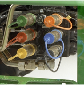 Six mid selective control valve (SCV) kit shown
 Six mid SCV quick coupler
This kit includes independent control valve (ICV) quick-couplers for mid-machine mounting. It enables the use of front-hydraulic-driven implements when a multifunctional lever and other parts are added to the machine.
3 Mid SCV Stack Screw In Quick Couplers - BRE10067
Six mid selective control valve (SCV) kit shown
Six mid SCV quick coupler
This kit includes independent control valve (ICV) quick-couplers for mid-machine mounting. It enables the use of front-hydraulic-driven implements when a multifunctional lever and other parts are added to the machine.
5th Remote Selective Control Valve with Electrohydraulic Controls - BRE10048
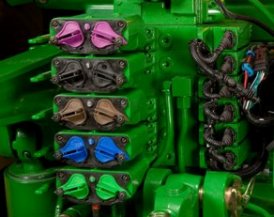 Five remote SCVs
The field-installed electronic SCV kits are made available for tractors needing additional SCVs. These kits provide metered flow rates and timed detents with pressure and load sense compensation. The additional SCV(s) can also be integrated into the Headland Management System.
The field-installed kit includes International Organization for Standardization (ISO) lever-assisted breakaway couplers and armrest control lever.
6th Remote Selective Control Valve with Electrohydraulic Controls - BRE10049
Five remote SCVs
The field-installed electronic SCV kits are made available for tractors needing additional SCVs. These kits provide metered flow rates and timed detents with pressure and load sense compensation. The additional SCV(s) can also be integrated into the Headland Management System.
The field-installed kit includes International Organization for Standardization (ISO) lever-assisted breakaway couplers and armrest control lever.
External SCV III Kit for Fender Extension - RE335072
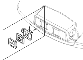
These switches allow for operator control of SCV functions while standing at the rear of the tractor. They are mounted on long wrap fenders only and provide an alternative location to operate specific implement functions where close view of the contact area is necessary.
Fourth Rear Remote SCV with Electro-Hydraulic Controls, Push/Pull Breakaway Couplers and High Pressure Relief Levers. - BRE10047
Five remote SCVs
The field-installed electronic SCV kits are made available for tractors needing additional SCVs. These kits provide metered flow rates and timed detents with pressure and load sense compensation. The additional SCV(s) can also be integrated into the Headland Management System.
The field-installed kit includes International Organization for Standardization (ISO) lever-assisted breakaway couplers and armrest control lever.
Mid Mount SCV, First & Second Remote (120 ml.) with TLS axle - RE340785
This kit is for adding only the SCVs to tractors that are not front hitch ready from the factory.
The addition of these front SCVs are required for the use of front hydraulically-powered implement accessories such as a hitch, loader, snow blower, or other accessories. Additional kits (such as software, mounting brackets, and joysticks) may be necessary depending on the accessory and functionality desired.
Mid Mount SCV, First & Second Remote (120 ml.) without TLS axle - RE340786
This kit is for adding only the SCVs to tractors that are not front hitch ready from the factory.
The addition of these front SCVs are required for the use of front hydraulically-powered implement accessories such as a hitch, loader, snow blower, or other accessories. Additional kits (such as software, mounting brackets, and joysticks) may be necessary depending on the accessory and functionality desired.
Mid Mount SCV, Third Remote (120 ml.) - RE340789
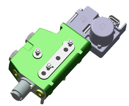 Third mid-mounted SCV
This kit provides additional hydraulic valve control for operation of implements that do not require a front hitch.
It allows for the installation of a third mid-mounted SCV.
Hydraulics
Hydraulic Motor Case Drain (Flush Face Coupler) Kit - BRE10281
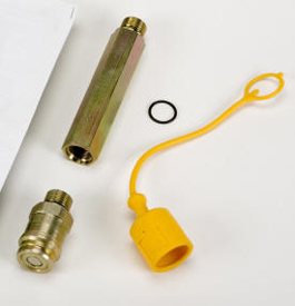 Flush face case drain coupler
For installing tractor case drain for vacuum motors. A motor seal drain kit (return to sump) protects the motor and shaft seal by allowing motor housing pressure to return back to hydraulic reservoir free of any back pressure. Handles up to 3 U.S. gallons per minute.
NOTE: All vacuum planters built after 1 May 2004 have hydraulic case drain vacuum motors. These motors have a flush-face case drain hose tip on the return oil line that must be routed to the tractor's sump/case drain port. The tractor requires a case drain coupler be installed in this port to accept the return hose.
This kit is required for operation of 1910 Commodity Air Cart and 1990 CCSTM hydraulically-driven fan.
Hydraulic Trailer Brake Kit - BRE10035
7030 Series Large-Frame Tractors can be equipped with trailer brakes
The trailer brakes can be dual line air, hydraulic, or both.
Trailer brakes, dual line air
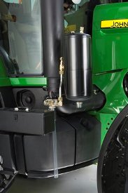 Air brake tank
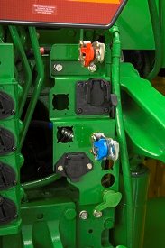 Air brake couplers
Code 9010, trailer brakes dual line air, provides the necessary components the brake system requires in order to hook up to an implement with air brakes. It allows the brakes to be set on the implement/trailer when parking the tractor and implement/trailer. The air brake system includes the compressor, tank, control valves and couplers. A field-installed option is also available for air brakes.
CAUTION: The agricultural tractor trailer air brake system is designed for use only with agricultural implements and agricultural trailers. This system is not compatible with the trailer air brake systems used by over-the-road vehicles and does not conform with the standards established for over-the-road trailer air contamination and electrical systems.
Trailer brakes, hydraulic valve
The hydraulic trailer brake system, code 9012, provides the necessary components the brake system requires in order to hook up to an implement with high-pressure hydraulic brakes. This is achieved by using delay valves that actuate the trailer brakes prior to tractor braking. A field-installed option is also available for air brakes.
Trailer brakes, dual line air and hydraulic valve
Factory-installed dual line air and hydraulic trailer brakes are provided with code 9062.
Implement Single Lever Control Lift Assist Kit - RE328941
The implement single-lever lift-assist kit is designed to be used with implements needing a separate lever to be used for lift-assist wheels.
Manifold Trailer Brakes - BRE10032
This kit is required to install hydraulic trailer brakes on tractors not equipped with front brakes or air trailer brakes from the factory.
Power Beyond Coupler, 1/2" Pressure & Return without 3 in 1 Hitch - BRE10072
Easy hookup of planters and other implements
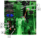 Auxiliary hydraulic couplers (8R shown)
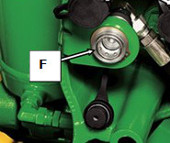 Auxiliary hydraulic couplers (8R shown)
- Pressure port
- Return ports
- Case drain port
- Load sense coupler
- Hitch valve
- Auxiliary hitch valve port (if equipped)
To assist hooking up large equipment where multiple connections are required, factory-installed auxiliary hydraulic couplers are available.
Auxiliary sump coupler
The sump coupler kit allows oil to return from the hydraulics motor at low pressures. This coupler is required for correct attachment to current-production seeding products with case drain lines. The connector in the sump port is not to be used to carry return flow from a function to the tractor.
Hydraulic motor return couplers
The hydraulic motor return couplers can be used as couplers for return oil flow, from hydraulic orbital motors and other devices to the tractor's low-pressure return port, labeled R on the tractor.
Use of this connector specifically in the return to sump port position is for hydraulic components that require a leak-off line connection to the tractor. Components and implements that require this typically are larger orbital motors that require a drain for seal protection. The connector in the sump port is not to be used to carry return flow from a function to the tractor.
Power beyond couplers
Power beyond provides live hydraulic power to equipment. This kit supplies oil pressure to implements when the engine is running.
Any implement using power beyond must have a way to control oil flow. Use an independent control valve that is pressure-and-flow compensating (supplied separately) to control the oil flow rate from this coupler set. Power-beyond functions require a load-sense signal to regulate pump pressure, therefore, a load-sense hydraulic line is used. Certain equipment may require modification.
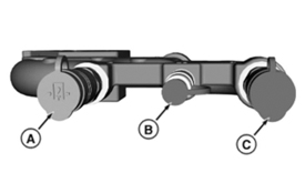 Optional auxiliary hydraulic equipment (9R shown)
The auxiliary hydraulic optional equipment includes the following:
A – Pressure coupler
B – Load sense coupler
C – Return coupler (motor return)
Power Beyond Coupler, 3/4" Pressure & Return without 3 in 1 Hitch - BRE10073
Easy hookup of planters and other implements
Auxiliary hydraulic couplers (8R shown)
Auxiliary hydraulic couplers (8R shown)
- Pressure port
- Return ports
- Case drain port
- Load sense coupler
- Hitch valve
- Auxiliary hitch valve port (if equipped)
To assist hooking up large equipment where multiple connections are required, factory-installed auxiliary hydraulic couplers are available.
Auxiliary sump coupler
The sump coupler kit allows oil to return from the hydraulics motor at low pressures. This coupler is required for correct attachment to current-production seeding products with case drain lines. The connector in the sump port is not to be used to carry return flow from a function to the tractor.
Hydraulic motor return couplers
The hydraulic motor return couplers can be used as couplers for return oil flow, from hydraulic orbital motors and other devices to the tractor's low-pressure return port, labeled R on the tractor.
Use of this connector specifically in the return to sump port position is for hydraulic components that require a leak-off line connection to the tractor. Components and implements that require this typically are larger orbital motors that require a drain for seal protection. The connector in the sump port is not to be used to carry return flow from a function to the tractor.
Power beyond couplers
Power beyond provides live hydraulic power to equipment. This kit supplies oil pressure to implements when the engine is running.
Any implement using power beyond must have a way to control oil flow. Use an independent control valve that is pressure-and-flow compensating (supplied separately) to control the oil flow rate from this coupler set. Power-beyond functions require a load-sense signal to regulate pump pressure, therefore, a load-sense hydraulic line is used. Certain equipment may require modification.
Optional auxiliary hydraulic equipment (9R shown)
The auxiliary hydraulic optional equipment includes the following:
A – Pressure coupler
B – Load sense coupler
C – Return coupler (motor return)
Lighting
Lights, Field Vision Xenon HID Rear Fender Light - RE269641
Xenon HID lights improve nighttime visibility
 HID lights
John Deere has taken advantage of advanced lighting technology. This lighting provides the operator with industry-leading performance in nighttime visibility.
The important part of the system is the use of Xenon high-intensity discharge (HID) bulbs. These bulbs provide extreme brightness and a daylight color output for excellent definition of the field. The performance of this system allows the operator to easily view as much as 250 percent farther ahead, compared to previous tractors. A further benefit is there are no filaments in the HID bulb. Bulb life is increased by as much as 10 times vs. filament-style bulbs.
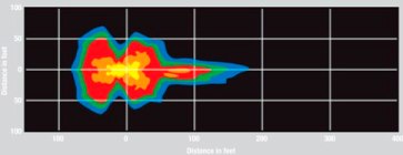 Standard lighting
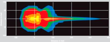 FieldVision lighting
Front FieldVision lighting
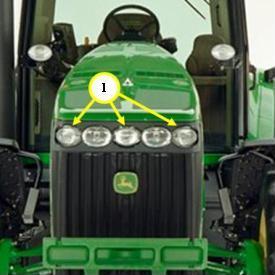 Front HID locations
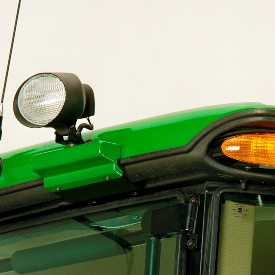 Roof lighting location
The front lighting package adds three high-intensity discharge (HID) lights to the front grille (see 1 in the image above). To further enhance all-around tractor lighting, there are two additional 65-W halogen work lights added to the left- and right-hand cab roof.
The center of the bulb has a semi-spot lens, and the outer light housings have a flood lens. In row-crop, the operator will notice there is a longer beam of light in the center for following marker furrows. The overall width of the lighting pattern for a non-row-crop operation will be obvious so tilled or seeded passes are easily identified. The inner, larger-diameter light assemblies are used for road transport and use conventional halogen 60-/55-W H4 bulbs. These larger light housings are also used in the base lighting system. With the dual-wattage H4 bulb, the operator will notice that there is a true automotive-style high/low function when operating in the road position.
The cab roof lights can be adjusted to aim to the side or rear of the tractor.
Rear FieldVision lighting
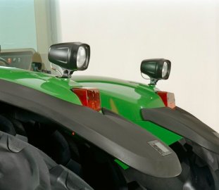 Rear FieldVision HID lighting
The premium HID lighting package (code 1720) adds two adjustable-position HID lights on the rear fenders.
Unlike aftermarket lights where the operating ballast is integral, these lights use a smaller housing with remote-mounted ballast. The smaller housing decreases obstruction for a clear view looking out the rear window. Using the light’s wide-angle flood lens will make it much easier to monitor the widest or longest equipment available.
Lights, Two Roof-Mounted 65W Halogen Front Flood Lights - RE326320
 Front roof-mounted floodlights
Side roof-mounted floodlights
Front roof-mounted floodlights
Side roof-mounted floodlights
Nighttime visibility can be improved on tractors with two roof-mounted front floodlights or two roof-mounted side floodlights.
Loader and Driving Light Package - RE334683
For additional transport visibility, install a rotary beacon light.
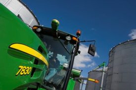 Rotary beacon light installed on 7030
 Rotary beacon light installed on 7020
Option code 9779 on the 7030 Series Large-Frame Tractors includes the rotary beacon light. The light features a fully-adjustable, double-clamp design that provides a more rigid vertical support stem.
Rotary beacon lights can be installed for additional transport visibility and commercial or governmental applications. The rotating, high-intensity light rests securely within an amber-colored lens.
Mirrors
External Mirrors, Electrically Adjustable Right Side and Left Side Conversion Kit - RE323407
The John Deere cabs offer several options for outside mirrors to increase rear visibility to assist in getting the view needed of variable-width implements, wagons, or carts. The wide-angle mirror options provide excellent overall rear visibility and are easily adjusted and telescope to maintain visibility for a variety of implements.
7R and 8R Series Tractor mirror options:
- Manually adjustable, single pane
- Wide angle, heated, electrically adjustable top pane, manual telescoping
- Wide angle, heated, electrically adjustable top pane, electrically telescoping
8RT Series Tractor mirror options:
- Manually adjustable, single pane
- Wide angle, heated, electrically adjustable top pane, electrically telescoping
9R and 9RX Series Tractor mirror options:
- Manually adjustable, single pane
- Wide angle, heated, electrically adjustable top pane, manual telescoping
- Wide angle, heated, electrically adjustable top pane, electrically telescoping
9RT Series Tractor mirror options:
- Manually adjustable, single pane
- Wide angle, heated, electrically adjustable top pane, electrically telescoping
Field-installed kits are also available to convert a manual mirror to an electrically adjustable mirror. See the attachment section for further information.
NOTE: Left-hand electrically telescoping mirrors are not compatible with 8RT and 9RT Tractors.
Manually adjustable, single pane mirrors
Wide-angle, heated, electrically adjustable top pane, manually telescoping mirrors
Wide-angle, heated, electrically adjustable top pane, electrically telescoping mirrors
Wide-angle, heated top pane, electrically adjustable top pane, non-telescoping left-hand mirror for 8RT and 9RT Series Tractors
External Mirrors, Electrically Telescoping and Heated Mirror Heads - BRE10041
The John Deere cabs offer several options for outside mirrors to increase rear visibility to assist in getting the view needed of variable-width implements, wagons, or carts. The wide-angle mirror options provide excellent overall rear visibility and are easily adjusted and telescope to maintain visibility for a variety of implements.
7R and 8R Series Tractor mirror options:
- Manually adjustable, single pane
- Wide angle, heated, electrically adjustable top pane, manual telescoping
- Wide angle, heated, electrically adjustable top pane, electrically telescoping
8RT Series Tractor mirror options:
- Manually adjustable, single pane
- Wide angle, heated, electrically adjustable top pane, electrically telescoping
9R and 9RX Series Tractor mirror options:
- Manually adjustable, single pane
- Wide angle, heated, electrically adjustable top pane, manual telescoping
- Wide angle, heated, electrically adjustable top pane, electrically telescoping
9RT Series Tractor mirror options:
- Manually adjustable, single pane
- Wide angle, heated, electrically adjustable top pane, electrically telescoping
Field-installed kits are also available to convert a manual mirror to an electrically adjustable mirror. See the attachment section for further information.
NOTE: Left-hand electrically telescoping mirrors are not compatible with 8RT and 9RT Tractors.
Manually adjustable, single pane mirrors
Wide-angle, heated, electrically adjustable top pane, manually telescoping mirrors
Wide-angle, heated, electrically adjustable top pane, electrically telescoping mirrors
Wide-angle, heated top pane, electrically adjustable top pane, non-telescoping left-hand mirror for 8RT and 9RT Series Tractors
External WIDE ANGLE mirrors, electronically telescoping and heated mirror heads - BRE10470
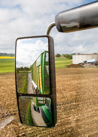 Full powered wide-angle mirror upgrade
See the benefits from a wider range of rear visibility with the wide-angle mirror kit. Regardless of how the tractor came equipped, this kit will upgrade the existing mirror to power extending arms, power rotating head, heated lens, and a standard mirror and wide-angle mirror for both the left and right side of the tractor. This kit is made from the same parts used in the John Deere factory and is bundled together for convenience.
Miscellaneous
Attachment, Hydraulic Oil Cooler Screen - BRE10212
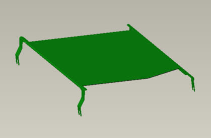 Hydraulic cooler screen
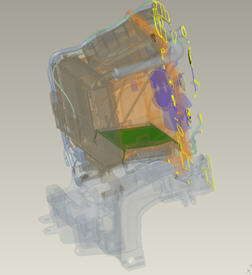 Hydraulic cooler screen mounting location
The hydraulic screen kit is available to protect the cooler from chaff and debris accumulation. Once the kit is installed, the rail system of the kit holds a mesh screen in place at the bottom of the machine. The screen can be easily removed/reinstalled by sliding it through the rails using the service handle.
Benefits include:
- Minimizes chaff introduction to hydraulic cooler fins
- Reduces cleaning time for cooling components
- Increases the efficiency of the cooler over time (assuming buildup of material is removed from the screen)
Guards, Undercarriage Crop Shield, IVT/PST - RE338192
The undercarriage crop shield kit is used to protect the undercarriage when working in crops where undercarriage damage is a concern such as in sugar cane or cotton. The undercarriage crop shield protects the transmission and wiring harness on the bottom side of the tractor.
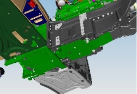 Undercarriage crop shield
The kit contains four shields and appropriate hardware to install between the front and rear axles and below the fuel tank. The shields are mounted on the bottom side of the chassis (transmission housing casting and oil pan) using existing tapped hole locations.
Security Door Lock Kit - AL71345
Custom key door locks
 Custom key door lock kit
Field-installed kit (AL71345) allows for a door handle to be installed that has a key different from the tractor ignition key.
Operator's Station
3-Pin Adaptor for Power Strip - RE67016
Power strip and accessories
Power strip kit
Power strip installed
The power strip provides six additional electrical outlets that give either permanent or ignition-key-controlled power for such items as:
-
Computers
-
Portable telephone chargers
-
Implement monitor
-
Implement supply
-
12-V and up to 30-amp total current can be taken from these outlets
The power strip is not a surge suppressor. Electrical equipment with program memory or capacity for data storage requires protection from the damage of electrical surges and spikes that could occur in systems without transient voltage protection.
Accessory Mounting Bracket - Long Bar - RE317435
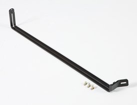 Accessories mounting bracket
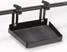 Tray kit
The accessories bracket is available for mounting monitors, phones, radios, and other accessories in one convenient location.
The bracket connects in the existing holes inside the cab.
Actively Cooled Refrigeration Unit - RE341704
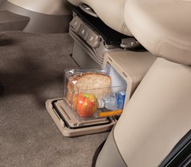 CommandView™ III cab refrigerator
The optional refrigerator, available for standard or premium cab models, offers improved operator comfort and accommodation. Located to the left of the operator’s seat, the refrigerator provides ample cooling capacity to keep food and beverages fresh. The large-capacity slide-out tray eases loading, unloading, and cleaning. The refrigerator is activated by turning the key to the on position or starting the tractor, and shuts off when the key is turned off.
Antenna Mount and Wiring for Business Band (2-Way) Radio - RE269615
This kit provides antenna mount, radio mounting plate, and wiring for a business band radio.
Carpet with foot throttle - RE346238
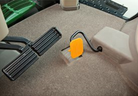 Carpet mat with foot throttle shown
Reduce cab noise and increase comfort with fabric flooring in the cab. This snag-resistant mat is color matched to the existing tractor cab interior and is easily removed and installed for quick cleaning. The die-cut carpet lays directly over the rubber floor in the cab and is a precise fit. A carpet mat is also available for tractors equipped with a foot throttle.
Carpet without foot throttle - RE556830
Carpet mat with foot throttle shown
Reduce cab noise and increase comfort with fabric flooring in the cab. This snag-resistant mat is color matched to the existing tractor cab interior and is easily removed and installed for quick cleaning. The die-cut carpet lays directly over the rubber floor in the cab and is a precise fit. A carpet mat is also available for tractors equipped with a foot throttle.
Cigar-Style Adapter for Power Strip - RE67014
Power strip and accessories
Power strip kit
Power strip installed
The power strip provides six additional electrical outlets that give either permanent or ignition-key-controlled power for such items as:
-
Computers
-
Portable telephone chargers
-
Implement monitor
-
Implement supply
-
12-V and up to 30-amp total current can be taken from these outlets
The power strip is not a surge suppressor. Electrical equipment with program memory or capacity for data storage requires protection from the damage of electrical surges and spikes that could occur in systems without transient voltage protection.
CommandARM Bracket - BRE10147
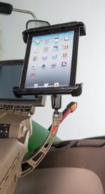 CommandARM bracket
 CommandARM bracket
The CommandARM bracket for Final Tier 4 (FT4) tractors offers a convenient way to mount a cell phone or tablet to the CommandARM for easy use of a mobile device. This bracket is not compatible with joystick-equipped tractors.
NOTE: Cell phone, tablet, and Ram mount hardware sold separately.
NOTE: This bracket is not compatible with joystick-equipped tractors.
Ethernet Adapter Cable (Square to Round) 800 mm (2.5 ft) - PFP12950
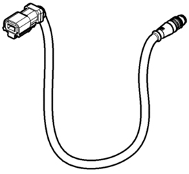
This cable connects the cornerpost Ehternet connector (square) to the GreenStar™ 3 2630 Display Ethernet connector (round). It is required for used with Remote Display Access (RDA), Wireless Data Transfer (WDT), and Machine Sync.
The square-to-round connector cable is 80-cm (31.5-in.) long.
Foot-Operated Speed Control, Wheel and Tracks - RE321017
 Speed control pedal
The speed control pedal increases productivity of the tractor/operator unit by allowing the operator better control of engine speed for loader work, maneuvering in tight spaces, and transport. This option provides the operator excellent modulation of engine speed on wheel tractors.
Infinitely Variable Transmission (IVT™) equipped tractors can have an automotive-type operation with the use of a speed control pedal. This is especially useful in transport applications. The speed control pedal and AutoClutch clutch action of the transmission are easily coordinated by the operator for smooth operation.
NOTE: This is also available as an accessory; please see Cab convenience accessories and kits.
Standard Connector with 1m (3-Foot) Cable for Power Strip - RE67013
Power strip and accessories
Power strip kit
Power strip installed
The power strip provides six additional electrical outlets that give either permanent or ignition-key-controlled power for such items as:
-
Computers
-
Portable telephone chargers
-
Implement monitor
-
Implement supply
-
12-V and up to 30-amp total current can be taken from these outlets
The power strip is not a surge suppressor. Electrical equipment with program memory or capacity for data storage requires protection from the damage of electrical surges and spikes that could occur in systems without transient voltage protection.
Sun Shade, Front Pull Down - RE261504
 Front pull-down sun shade
The pull-down shade for the front windshield improves operator visibility on sunny days by blocking the sun's bright light and reducing glare. The pull-down sunshade allows the operator flexibility in the amount of window coverage desired through an infinitely adjustable range of movement and more positive friction detents found in a scissors-style linkage. The sun shade is included in all comfort and convenience cab packages.
Sun Shade, Rear or Right Hand - RE562587
Front pull-down sun shade
The pull-down shade for the front windshield improves operator visibility on sunny days by blocking the sun's bright light and reducing glare. The pull-down sunshade allows the operator flexibility in the amount of window coverage desired through an infinitely adjustable range of movement and more positive friction detents found in a scissors-style linkage. The sun shade is included in all comfort and convenience cab packages.
Pick-up Weights
Power Take-off (Pto)
Front PTO 20-spline 1.75 in. front PTO stub shaft (flange) - RE313418
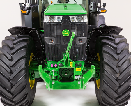 Front PTO
For increased versatility, two 1000-rpm front PTO options are available from the factory for 7R and 8R Series Tractors equipped with the John Deere front hitch.
- Type 2, 1000-rpm (counterclockwise as seen from front), 35-mm (1 3/8-in.), 21-spline front PTO
- Type 3, 1000-rpm (counterclockwise as seen from front), 45-mm (1 ¾-in.) 20-spline front PTO (available through Parts only)
Front PTO features include:
- The ability to be incorporated with iTEC™ sequences
- Three choices of engagement modulation: auto, low, and high
- Integrated controls
- Cornerpost display indicators
- Bolt-on shaft makes it easy to change shafts if necessary.
- Remote PTO engagement
7R specific features:
- 130 kW (175 hp)
- Integrated with all transmissions
- PTO disconnect for efficiency
- Requires Triple-Link Suspension (TLS™) front axle
8R specific features:
- 112 kW (150 hp)
- Integrated with the infinitely variable transmission (IVT™)
- Requires Independent-Link Suspension (ILS™) with front brakes
Intelligent Power Management (IPM)
IPM is compatible with 7R and 8R Series Tractors equipped with a front PTO option. The front PTO, rear PTO, or transport speeds can activate IPM on 7R Tractors. However, on 8R Tractors, IPM is only activated by the rear PTO or by transport speeds. For example:
- A front snow blower will not benefit from IPM on an 8R since the front PTO alone will not activate IPM.
- A triple-mounted mower-conditioner will benefit from IPM as high power levels are transmitted via the rear PTO. The front mower-conditioner will have 112 kW (150 hp) available to it on an 8R, which is adequate to operate these mowers in most crop conditions.
- See Intelligent Power Management for more information.
PTO disconnect on 7 Family Tractors
Disconnecting the PTO drive to the PTO box when not in use increases tractor efficiency by reducing:
- Power requirements, which saves nearly 70 percent of power required to run the PTO disengaged
- Wear on components of the PTO box; components are not moving when the PTO is disconnected
Refer to the Operator’s Manual for instructions on how to disconnect the PTO when not in operation.
Front PTO operation
Remote control at front of tractor
Front PTO engagement is actuated through an engagement switch similar to the rear PTO located on the CommandARM™ controls.
- PTO clutch is electronically activated with automatic torque modulation.
- PTO modulation is selectable through the CommandCenter™ display.
- To activate the PTO remotely, select the remote PTO enable button in Generation 4 CommandCenter display, push down and forward on the front PTO switch in the cab and use the remote control at the front of the tractor.
NOTE: For the 8R Series, if the tractor is equipped with a front PTO, additional IPM power will transfer through the front PTO. However, IPM activation is only sensed through the rear PTO. Adequate load must be sensed on the rear PTO in order for IPM to activate.
Front PTO 21-spline 1.375 in. PTO stub shaft (flange) - RE313419
Front PTO
For increased versatility, two 1000-rpm front PTO options are available from the factory for 7R and 8R Series Tractors equipped with the John Deere front hitch.
- Type 2, 1000-rpm (counterclockwise as seen from front), 35-mm (1 3/8-in.), 21-spline front PTO
- Type 3, 1000-rpm (counterclockwise as seen from front), 45-mm (1 ¾-in.) 20-spline front PTO (available through Parts only)
Front PTO features include:
- The ability to be incorporated with iTEC™ sequences
- Three choices of engagement modulation: auto, low, and high
- Integrated controls
- Cornerpost display indicators
- Bolt-on shaft makes it easy to change shafts if necessary.
- Remote PTO engagement
7R specific features:
- 130 kW (175 hp)
- Integrated with all transmissions
- PTO disconnect for efficiency
- Requires Triple-Link Suspension (TLS™) front axle
8R specific features:
- 112 kW (150 hp)
- Integrated with the infinitely variable transmission (IVT™)
- Requires Independent-Link Suspension (ILS™) with front brakes
Intelligent Power Management (IPM)
IPM is compatible with 7R and 8R Series Tractors equipped with a front PTO option. The front PTO, rear PTO, or transport speeds can activate IPM on 7R Tractors. However, on 8R Tractors, IPM is only activated by the rear PTO or by transport speeds. For example:
- A front snow blower will not benefit from IPM on an 8R since the front PTO alone will not activate IPM.
- A triple-mounted mower-conditioner will benefit from IPM as high power levels are transmitted via the rear PTO. The front mower-conditioner will have 112 kW (150 hp) available to it on an 8R, which is adequate to operate these mowers in most crop conditions.
- See Intelligent Power Management for more information.
PTO disconnect on 7 Family Tractors
Disconnecting the PTO drive to the PTO box when not in use increases tractor efficiency by reducing:
- Power requirements, which saves nearly 70 percent of power required to run the PTO disengaged
- Wear on components of the PTO box; components are not moving when the PTO is disconnected
Refer to the Operator’s Manual for instructions on how to disconnect the PTO when not in operation.
Front PTO operation
Remote control at front of tractor
Front PTO engagement is actuated through an engagement switch similar to the rear PTO located on the CommandARM™ controls.
- PTO clutch is electronically activated with automatic torque modulation.
- PTO modulation is selectable through the CommandCenter™ display.
- To activate the PTO remotely, select the remote PTO enable button in Generation 4 CommandCenter display, push down and forward on the front PTO switch in the cab and use the remote control at the front of the tractor.
NOTE: For the 8R Series, if the tractor is equipped with a front PTO, additional IPM power will transfer through the front PTO. However, IPM activation is only sensed through the rear PTO. Adequate load must be sensed on the rear PTO in order for IPM to activate.
Mounting kit for front power take-off (PTO) - BRE10355
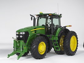 Mounting kit for front PTO with TLS
Radio
Standard Radio Package - BRE10038
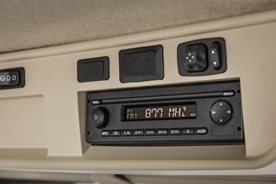 Radio
Radio
John Deere radio packages provide powerful performance with standard four-speaker systems. The standard radio package features easy-to-use operator controls located on the CommandCenter™ display and at the radio faceplate. AM/FM and weatherband tuner allows operators to stay tuned to their favorite radio stations and keep current with ever-changing weather patterns. An auxiliary input for connecting an external media source is conveniently located on the right-side console.
The premium radio package adds to these great features with Bluetooth® to connect with compatible media devices and a USB input for connecting external media sources. A subwoofer is also available in this package to increase the operator experience within the cab.
Both radio packages help create a comfortable operator environment for long hours in the cab.
Standard radio package
- AM/FM and weatherband tuner (NOAA broadcast channels)
- External antenna
- Remote controls through the CommandARM™ controls (volume, mute, channel up/down)
- CommandCenter display with station selection, volume level, and station presets
- Auxiliary input (3.5 mm [0.14 in.]) on right-side console
- Four coaxial speakers
Premium radio package*
- AM/FM, weatherband (NOAA broadcast channels), and worldwide premium tuner
- External antenna
- Remote controls through CommandARM (volume, mute, channel up/down)
- CommandCenter display with station selection, volume level, and station presets
- Universal serial bus (USB) input
- Auxiliary input on right-side console
- Bluetooth capable with microphone (allows phone and streaming audio)
- Four coaxial speakers
- Subwoofer
*XM Satellite functionality for premium radio needs to be upgraded by purchasing the XM antenna, XM receiver, brackets, and wiring harnesses via a kit from your local John Deere dealer.
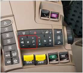 Radio controls
Bosch is a trademark of Robert Bosch GmBH. Bluetooth is a trademark of Bluetooth SIG Incorporated. XM is a trademark of XM Satellite Radio Incorporated. Delco is a trademark of General Motors LLC.
Rear Hitch
80mm (3.15 in.) Ball for 3-in1 Hitch - RE578864
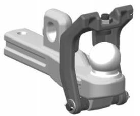 RE583627 - Coupling insert
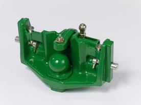 RE578864 - Height adjustable hitch
These kits allow ball-type receivers (used on wagons and other pull behind implements) to be safely attached and locked into position on large tractors.
- Check ball height and implement/wagon requirements for correct height of the receiver.
- Not approved for use with the DN345 drawn dry spreader. Check BRE10216, RE268625, and RE283958 for approved DN345 ball-type drawbar.
Hitch, Wagon (Manual Coupling) for 3-in-1 Hitch - AL222029
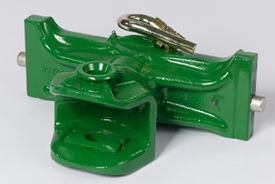
The manual wagon hitch with 30-mm (1.18-in.) pin will insert into the hitch bracket without the use of tools.
Benefits include:
- Hitch exchange without any tools
- High-quality John Deere products
- Excellent driving comfort and easy coupling
Pick-up Hitch Hook End - R559513
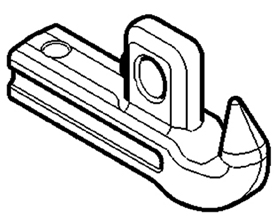
Add the ability to connect to additional implement connection types with this pick-up hitch hook end, and increase versatility in the tractor's towing options.
Piton Fix for 3-in-1 Hitch - RE578863
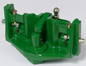
The piton fix can be inserted into the hitch bracket without the use of any tools. With the piton-fix wagon hitch, it is possible to pull trailers or implements with high vertical loads.
Benefits include:
- Hitch exchange without any tools
- Large trailers and implements with high vertical load can be pulled
- Excellent driving comfort and easy coupling.
Rear Hitch Premium Controls Upgrade Kit - BRE10144
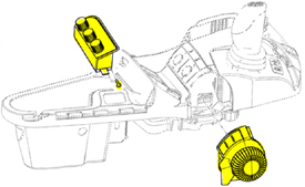
This kit provides additional (premium upgrade) controls for operating the rear hitch from the operator's seat.
Rear Hitch Quik-Coupler (Convertible Category 3/3N) - RE180668
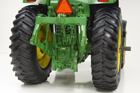 Rear hitch Quik-Coupler kit
Rear hitch Quik-Coupler kit compatible with 8X30, 7X00, 8X00, 8X00T, 7610, 7710, 7810, 8X10, 8X10T, 8X20, 8X20T, 7X20, 7X30, 6170R, 6190R, 6210R, 6140R, 6150R, 8R, 8RT, and 7R Series Tractors.
Category 3/3N rear rockshaft and hitch with adjustable drawbar, to be installed on tractors ordered less rockshaft.
Rear Hydraulic Center Link, 90mm Ball Type (Cat 3) - RE330573
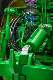 Hydraulic rear center-link
The 7R Series Tractors offer a Category 3 rear hydraulic center-link for all models. All wheel models of the 8R Series Tractor offer a Category 4 rear hydraulic center-link, in addition to a Category 3 center-link option for models 8295R and below.
The rear hydraulic center-link helps to ease the installation of hitch-mounted implements and makes fine adjustment of the top link effortless.
Center-link adjustments can be made in the field by using the control for the third selective control valve (SCV) or from the CommandCenter™ display. Adjustments may also be made using external controls on the rear fenders.
NOTE: These options are only compatible with fender extensions.
Secondary Rear Hitch Setup Control - BRE10326
This kit provides additional (premium upgrade) controls for operating the rear hitch from the operator's seat.
Rear Wheel Weights
Weight, Wheel Kit 554 kg (1221 lb) - BL15071
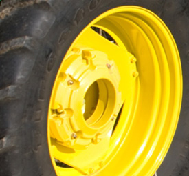 Rear-wheel weight
Cast-iron wheel weights provide added ballast at the tires for increased traction and stability.
Seat
Seat Belt Kit - RE298942
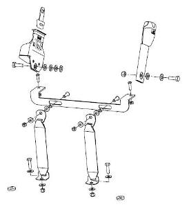 Seat belt for 8R Series Tractors
The 3-in. field-installed seat belt kit is designed for use with the 8R and 8RT Series Tractor operator seats. The seat belt kit is offered to meet regulations that require a seat belt anchorage force similar to the SAE J386 (including previous versions up to 22.2 kN anchorage strength), IOS 6683, and OSHA requirements (29CFR1926.602) for earthmoving operations and non-agricultural tractor operations.
NOTE: John Deere recommends reviewing the seat belt kit performance capabilities to ensure compliance with local, state, regional, and national requirements.
Trailer Brake
Hydraulic Trailer Brake Kit - BRE10398
The 7R Series and 8R Series Tractors offer dual-line hydraulic trailer brakes, dual-line air trailer brakes, or dual-line air and dual-line hydraulic trailer brakes, which allow the tractor braking system to connect to implements with high-pressure air or hydraulic brakes. Both systems automatically balance the brake pressure of both the tractor and implement to provide comfortable braking performance.
Trailer brake settings are fully customizable by adjusting gain and pre-brake settings. Trailer brake gain will give customers the ability to adjust how aggressive the trailer brakes are as the tractor brake pedal is depressed. Pre-brake adjustment will allow operators to adjust when the brakes are initiated in reference to the tractor brake pedal being depressed. This along with AutoClutch™ system settings will help the operator achieve optimum braking performance of both tractor and implement. Operators will also be able to test the trailer brake park release while the tractor is still in park during connecting and pre-trip activities.
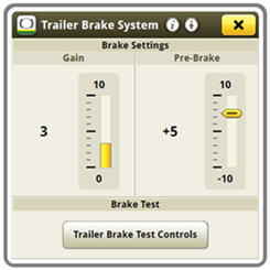 Adjusting gain and pre-brake settings
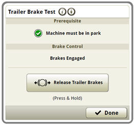 Testing the trailer brake park release
Factory options include dual-line hydraulic trailer brakes, dual-line air trailer brakes, or dual-line air and dual-line hydraulic trailer brake systems. The dual-line hydraulic trailer brake option is also available as a field-installed kit.
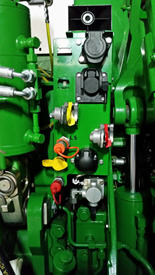 Trailer brake connections – 8R shown
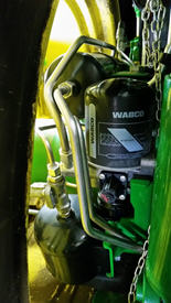 Air trailer brake tank and dryer – 8R shown
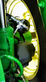 Air trailer brake tank – 8R shown
Hydraulic trailer brakes for 8RT Series Tractors are offered field installed only.
Dual-line hydraulic trailer brake system
Permits the use of hydraulic trailer brakes on the tractor. This system connects directly to the tractor’s hydraulic circuit and does not require the use of an auxiliary oil reservoir.
Hydraulic trailer brake system includes:
- Rear tractor line hydraulic couplers
Dual-line air trailer brake system
Permits the use of air trailer brakes on the tractor.
Air trailer brake system includes:
- Compressor
- Tank
- Air dryer
- Control valves
- Two line couplers
CAUTION: The agricultural tractor air trailer brake system is designed for use only with agricultural implements and agricultural trailers. This system is not compatible with the air trailer brake system used by over-the-road vehicles and does not conform to the standards established for over-the-road air trailer brake contamination and electrical systems.
Dual-line air and dual-line hydraulic trailer brake system
Permits the use of hydraulic or air brakes on the tractor. This system connects directly to the tractor’s hydraulic circuit and does not require the use of an auxiliary oil reservoir.
Air and hydraulic trailer brake system includes:
- Compressor
- Tank
- Air dryer
- Control valves
- Two line couplers
- Rear tractor line hydraulic couplers
CAUTION: The agricultural tractor air trailer brake system is designed for use only with agricultural implements and agricultural trailers. This system is not compatible with the air trailer brake system used by over-the-road vehicles and does not conform to the standards established for over-the-road air trailer brake contamination and electrical systems.
Hydraulic Trailer Brake Kit - BRE10397
The 7R Series and 8R Series Tractors offer dual-line hydraulic trailer brakes, dual-line air trailer brakes, or dual-line air and dual-line hydraulic trailer brakes, which allow the tractor braking system to connect to implements with high-pressure air or hydraulic brakes. Both systems automatically balance the brake pressure of both the tractor and implement to provide comfortable braking performance.
Trailer brake settings are fully customizable by adjusting gain and pre-brake settings. Trailer brake gain will give customers the ability to adjust how aggressive the trailer brakes are as the tractor brake pedal is depressed. Pre-brake adjustment will allow operators to adjust when the brakes are initiated in reference to the tractor brake pedal being depressed. This along with AutoClutch™ system settings will help the operator achieve optimum braking performance of both tractor and implement. Operators will also be able to test the trailer brake park release while the tractor is still in park during connecting and pre-trip activities.
Adjusting gain and pre-brake settings
Testing the trailer brake park release
Factory options include dual-line hydraulic trailer brakes, dual-line air trailer brakes, or dual-line air and dual-line hydraulic trailer brake systems. The dual-line hydraulic trailer brake option is also available as a field-installed kit.
Trailer brake connections – 8R shown
Air trailer brake tank and dryer – 8R shown
Air trailer brake tank – 8R shown
Hydraulic trailer brakes for 8RT Series Tractors are offered field installed only.
Dual-line hydraulic trailer brake system
Permits the use of hydraulic trailer brakes on the tractor. This system connects directly to the tractor’s hydraulic circuit and does not require the use of an auxiliary oil reservoir.
Hydraulic trailer brake system includes:
- Rear tractor line hydraulic couplers
Dual-line air trailer brake system
Permits the use of air trailer brakes on the tractor.
Air trailer brake system includes:
- Compressor
- Tank
- Air dryer
- Control valves
- Two line couplers
CAUTION: The agricultural tractor air trailer brake system is designed for use only with agricultural implements and agricultural trailers. This system is not compatible with the air trailer brake system used by over-the-road vehicles and does not conform to the standards established for over-the-road air trailer brake contamination and electrical systems.
Dual-line air and dual-line hydraulic trailer brake system
Permits the use of hydraulic or air brakes on the tractor. This system connects directly to the tractor’s hydraulic circuit and does not require the use of an auxiliary oil reservoir.
Air and hydraulic trailer brake system includes:
- Compressor
- Tank
- Air dryer
- Control valves
- Two line couplers
- Rear tractor line hydraulic couplers
CAUTION: The agricultural tractor air trailer brake system is designed for use only with agricultural implements and agricultural trailers. This system is not compatible with the air trailer brake system used by over-the-road vehicles and does not conform to the standards established for over-the-road air trailer brake contamination and electrical systems.
Weights
Weight, Wheel Kit 2x205 kg (425 lb) - BL15076
Rear-wheel weight
Cast-iron wheel weights provide added ballast at the tires for increased traction and stability.
Wheel Weights
Starter Weight, Wheel, 72 kg (159 lb) - R167153
For operators requiring additional ballast or additional traction on the rear axle
72-kg (159-lb), 205-kg (452-lb), 625-kg (1378-lb), and 970-kg (2138-lb) cast rear-wheel weights are available for the 7R and 8R Series Tractors. The attaching hardware for all rear-wheel weight options may be ordered through parts.
The range of rear-wheel weights can provide the proper amount of rear axle ballast for a variety of applications. The addition of this ballast will increase traction on the rear axle of the tractor. These weights can also be used to counterbalance the effect of adding additional weight on the front axle in the form of a front weight support, front hitch, front spray tanks, and front-end loaders.
205-kg (452-lb) weight
The 205-kg (452-lb) cast rear-wheel weight is offered individually as attachment R07782. The 72-kg (159-lb) starter weight (R167153) must be installed prior to the 205-kg (452-lb) weight on rear steel wheels. This practice is optional on cast wheels; however, most weight packages will be configured this way.
625-kg (1378-lb) weight
R553540 includes one 625-kg (1378-lb) cast inner rear-wheel weight. This weight is to be used on the inside of the rear wheel assembly. This option can be stacked on a double-flat cast hub, with a 70-kg (154-lb) starter ring on the outside.
70-kg (154-lb) weight
BRE10026 features a 70-kg (154-lb) starter weight. The starter weight and guide lugs provide improved installation and removal of the 900-kg (1984-lb) weight. This weight can be used individually on the outside of the steel, dual rims on rack-and-pinion axles, or on the outside of the double-flat, single-taper wheel hub. For the approved cast hubs, can also be used with the inner cast weights as well.
NOTE: Use on the outer side of approved cast hubs will limit dual tire and spacing capability.
900-kg (1984-lb) weight
Individual R341378 900-kg (1984-lb) weights ordered through Parts. The 70-kg (154-lb) starter weight is required for installation, and provides guide lugs for improved installation and removal of the 900-kg (1984-lb) weight. 900-kg (1984-lb) weight ballast option is compatible with steel, dual wheels with rim diameters of 106.7, 116.8 cm, or 127 cm (42 in., 46 in., or 50 in.). This allows the weights to be added to only the outer rear dual on a rack-and-pinion axle and double-flat axle with single-taper hub.
NOTE: This weight option is not compatible with 96.5-cm or 137.2-cm (38-in. or 54-in.) wheels.
Weight, Wheel 205 kg (452 lb) - R207782
For operators requiring additional ballast or additional traction on the rear axle
72-kg (159-lb), 205-kg (452-lb), 625-kg (1378-lb), and 970-kg (2138-lb) cast rear-wheel weights are available for the 7R and 8R Series Tractors. The attaching hardware for all rear-wheel weight options may be ordered through parts.
The range of rear-wheel weights can provide the proper amount of rear axle ballast for a variety of applications. The addition of this ballast will increase traction on the rear axle of the tractor. These weights can also be used to counterbalance the effect of adding additional weight on the front axle in the form of a front weight support, front hitch, front spray tanks, and front-end loaders.
205-kg (452-lb) weight
The 205-kg (452-lb) cast rear-wheel weight is offered individually as attachment R07782. The 72-kg (159-lb) starter weight (R167153) must be installed prior to the 205-kg (452-lb) weight on rear steel wheels. This practice is optional on cast wheels; however, most weight packages will be configured this way.
625-kg (1378-lb) weight
R553540 includes one 625-kg (1378-lb) cast inner rear-wheel weight. This weight is to be used on the inside of the rear wheel assembly. This option can be stacked on a double-flat cast hub, with a 70-kg (154-lb) starter ring on the outside.
70-kg (154-lb) weight
BRE10026 features a 70-kg (154-lb) starter weight. The starter weight and guide lugs provide improved installation and removal of the 900-kg (1984-lb) weight. This weight can be used individually on the outside of the steel, dual rims on rack-and-pinion axles, or on the outside of the double-flat, single-taper wheel hub. For the approved cast hubs, can also be used with the inner cast weights as well.
NOTE: Use on the outer side of approved cast hubs will limit dual tire and spacing capability.
900-kg (1984-lb) weight
Individual R341378 900-kg (1984-lb) weights ordered through Parts. The 70-kg (154-lb) starter weight is required for installation, and provides guide lugs for improved installation and removal of the 900-kg (1984-lb) weight. 900-kg (1984-lb) weight ballast option is compatible with steel, dual wheels with rim diameters of 106.7, 116.8 cm, or 127 cm (42 in., 46 in., or 50 in.). This allows the weights to be added to only the outer rear dual on a rack-and-pinion axle and double-flat axle with single-taper hub.
NOTE: This weight option is not compatible with 96.5-cm or 137.2-cm (38-in. or 54-in.) wheels.
Weight, Wheel 625 kg (1378 lb) - R553540
For operators requiring additional ballast or additional traction on the rear axle
72-kg (159-lb), 205-kg (452-lb), 625-kg (1378-lb), and 970-kg (2138-lb) cast rear-wheel weights are available for the 7R and 8R Series Tractors. The attaching hardware for all rear-wheel weight options may be ordered through parts.
The range of rear-wheel weights can provide the proper amount of rear axle ballast for a variety of applications. The addition of this ballast will increase traction on the rear axle of the tractor. These weights can also be used to counterbalance the effect of adding additional weight on the front axle in the form of a front weight support, front hitch, front spray tanks, and front-end loaders.
205-kg (452-lb) weight
The 205-kg (452-lb) cast rear-wheel weight is offered individually as attachment R07782. The 72-kg (159-lb) starter weight (R167153) must be installed prior to the 205-kg (452-lb) weight on rear steel wheels. This practice is optional on cast wheels; however, most weight packages will be configured this way.
625-kg (1378-lb) weight
R553540 includes one 625-kg (1378-lb) cast inner rear-wheel weight. This weight is to be used on the inside of the rear wheel assembly. This option can be stacked on a double-flat cast hub, with a 70-kg (154-lb) starter ring on the outside.
70-kg (154-lb) weight
BRE10026 features a 70-kg (154-lb) starter weight. The starter weight and guide lugs provide improved installation and removal of the 900-kg (1984-lb) weight. This weight can be used individually on the outside of the steel, dual rims on rack-and-pinion axles, or on the outside of the double-flat, single-taper wheel hub. For the approved cast hubs, can also be used with the inner cast weights as well.
NOTE: Use on the outer side of approved cast hubs will limit dual tire and spacing capability.
900-kg (1984-lb) weight
Individual R341378 900-kg (1984-lb) weights ordered through Parts. The 70-kg (154-lb) starter weight is required for installation, and provides guide lugs for improved installation and removal of the 900-kg (1984-lb) weight. 900-kg (1984-lb) weight ballast option is compatible with steel, dual wheels with rim diameters of 106.7, 116.8 cm, or 127 cm (42 in., 46 in., or 50 in.). This allows the weights to be added to only the outer rear dual on a rack-and-pinion axle and double-flat axle with single-taper hub.
NOTE: This weight option is not compatible with 96.5-cm or 137.2-cm (38-in. or 54-in.) wheels.
Wheel Weights
Starter Weight, Wheel, 70 kg (154 lb) - BRE10026
For operators requiring additional ballast or additional traction on the rear axle
72-kg (159-lb), 205-kg (452-lb), 625-kg (1378-lb), and 970-kg (2138-lb) cast rear-wheel weights are available for the 7R and 8R Series Tractors. The attaching hardware for all rear-wheel weight options may be ordered through parts.
The range of rear-wheel weights can provide the proper amount of rear axle ballast for a variety of applications. The addition of this ballast will increase traction on the rear axle of the tractor. These weights can also be used to counterbalance the effect of adding additional weight on the front axle in the form of a front weight support, front hitch, front spray tanks, and front-end loaders.
205-kg (452-lb) weight
The 205-kg (452-lb) cast rear-wheel weight is offered individually as attachment R07782. The 72-kg (159-lb) starter weight (R167153) must be installed prior to the 205-kg (452-lb) weight on rear steel wheels. This practice is optional on cast wheels; however, most weight packages will be configured this way.
625-kg (1378-lb) weight
R553540 includes one 625-kg (1378-lb) cast inner rear-wheel weight. This weight is to be used on the inside of the rear wheel assembly. This option can be stacked on a double-flat cast hub, with a 70-kg (154-lb) starter ring on the outside.
70-kg (154-lb) weight
BRE10026 features a 70-kg (154-lb) starter weight. The starter weight and guide lugs provide improved installation and removal of the 900-kg (1984-lb) weight. This weight can be used individually on the outside of the steel, dual rims on rack-and-pinion axles, or on the outside of the double-flat, single-taper wheel hub. For the approved cast hubs, can also be used with the inner cast weights as well.
NOTE: Use on the outer side of approved cast hubs will limit dual tire and spacing capability.
900-kg (1984-lb) weight
Individual R341378 900-kg (1984-lb) weights ordered through Parts. The 70-kg (154-lb) starter weight is required for installation, and provides guide lugs for improved installation and removal of the 900-kg (1984-lb) weight. 900-kg (1984-lb) weight ballast option is compatible with steel, dual wheels with rim diameters of 106.7, 116.8 cm, or 127 cm (42 in., 46 in., or 50 in.). This allows the weights to be added to only the outer rear dual on a rack-and-pinion axle and double-flat axle with single-taper hub.
NOTE: This weight option is not compatible with 96.5-cm or 137.2-cm (38-in. or 54-in.) wheels.
Wheelspacers
Rear Dual Hub Extension, 127 mm (5 in.) - AR194744
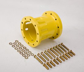 Hub extension kit
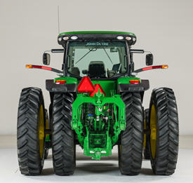 8R Series Tractor with dual hubs
Hub extensions mount to the dual/triple hub to extend the steel wheel tread width for exact dual/triple-wheel spacing for 20-in. through 40-in. rows.
Rear Dual Hub Extension, 254 mm (10 in.) - AR190666
Hub extension kit
8R Series Tractor with dual hubs
Hub extensions mount to the dual/triple hub to extend the steel wheel tread width for exact dual/triple-wheel spacing for 20-in. through 40-in. rows.
Rear Dual Hub Extension, 330 mm (13 in.) - AR190668
Hub extension kit
8R Series Tractor with dual hubs
Hub extensions mount to the dual/triple hub to extend the steel wheel tread width for exact dual/triple-wheel spacing for 20-in. through 40-in. rows.
Rear Dual Hub Extension, 381 mm (15 in.) - AR190669
Hub extension kit
8R Series Tractor with dual hubs
Hub extensions mount to the dual/triple hub to extend the steel wheel tread width for exact dual/triple-wheel spacing for 20-in. through 40-in. rows.
Three Meter Front Wheel Spacer (425 mm Bolt Circle Hub) - RE267658
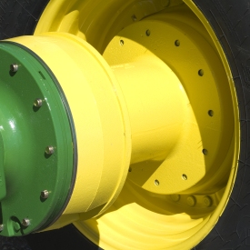 Front wheel spacer
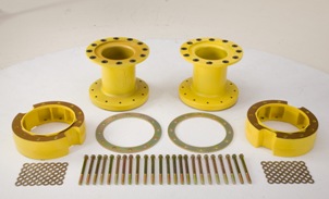 3-m (118-in.) front-wheel spacer kit
3-m (118-in.) front-wheel spacing kits are available for John Deere 7R and 8R Series Tractors in order to reach 3-m (118-in.) row spacing.
NOTE: No longer compatible with 7R and 8R Series Tractors with Active Command Steering (ACS).
See below for tractor applications and limitations.
Large-frame 7020/7030/7R Series Tractor restrictions
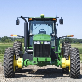 7030 Series Tractor
- 1150 or 1300 front axle with 12-bolt hub – mechanical front-wheel drive (MFWD) with or without Triple-Link Suspension (TLS™) tractor suspension
- No frame ballast (cast ballast can be used on rear axle and liquid in front tires)
- No front hitches, loaders, implements, or spray tanks of any kind allowed
- Not compatible with front brakes
- Extended wheel position will reduce turn angle on 7R Tractors
- Tractor ballast and speed of operation must not exceed tire manufacturer's recommendations for front tire load and speed
8020/8030/8R Series Tractor restrictions
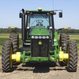 8030 Series Tractor
-
Independent-Link Suspension (ILS™) vehicle suspension or 1500 Series axle
-
Single front tires only
-
3-m (118-mm) rear axle
-
No front hitches, loaders, implements, or spray tanks of any kind allowed
-
Tractor ballast and speed of operation must not exceed tire manufacturer's recommendations for front tire load and speed
Prior to 8R late model year 2014 (serial numbers below 90000), all 8 Series and 8R Series Tractors utilized the same 3-m (118-in.) front-wheel spacer: RE267658.
For late model year 2014 and newer (serial numbers above 90000), there are two distinct attachments for attaining 3-m (118-in.) spacing: RE267658 and BRE10130.
- Attachment required for tractors equipped with a 1500 front axle: RE267658
- Attachment required for tractors equipped with an ILS front axle:
8245R |
8270R |
8295R |
8320R |
8345R |
8370R |
8400R |
|
Model year 2014 (90000) |
RE267658* |
BRE10130* |
|||||
Model year 2015 (100000) |
RE267658* |
BRE10130* |
|||||
NOTE: No longer compatible with 7R and 8R Series Tractors with ACS.
The 7250R Tractor; available at all the following C & B Locations:
- Billings, MT
- Blackfoot, ID
- Jackson, MN
- Lake Park, IA
- Chamberlain, SD
- Edgerton, MN
- St. James, MN
- Luverne, MN
- Circle, MT
- Roscoe, SD
- Yankton, SD
- Freeman, SD
- Corsica, SD
- Miles City, MT
- Worthington, MN
- Culbertson, MT
- Rexburg, ID
- Gettysburg, SD
- Miller, SD
- Storm Lake, IA
- Wagner, SD
- Mitchell, SD
- Powell, WY
- Plentywood, MT
- Glasgow, MT
- Truman, MN
- Selby, SD
- Pipestone, MN
- Tracy, MN
- Glendive, MT
- Sheridan, WY
- Spencer, IA
- Slayton, MN
- Ida Grove, IA
- Sibley, IA
- Sioux Falls, SD Turf CCE Store
- Sioux Falls, SD (FSO Office)
- Idaho Falls, ID